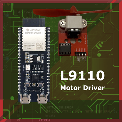
How to Control Motors with L9110 and ESP32 – A Step-by-Step Guide
Learn how to control DC motors with the ESP32 and L9110 motor driver. This beginner-friendly guide covers connections, coding, and tips to get your motors running in no time!
In this guide, we'll look at using the ESP32 with the L9110 motor driver, a simple but effective module for controlling DC motors. This combination offers an accessible way to add motor control to your projects, making it ideal to build smart robots, automation systems, and more. Before diving into the details, let’s take a closer look at the L9110 motor driver and its benefits.
Why would you use L9110 Motor Driver #
The L9110 motor driver is a compact and reliable module designed for controlling small DC motors and even stepper motors. It’s based on an H-bridge circuit, allowing you to control the direction and speed of connected motors. This is especially valuable for robotics projects, as it lets you create complex movements and change directions easily. The L9110 can operate with a wide range of input voltages, typically between 2.5V to 12V, making it suitable for various motor types.
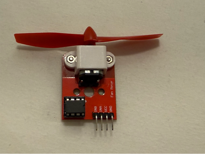
One of the main advantages of the L9110 is its simplicity and cost-effectiveness. It has just a few control pins, making it easy to integrate into circuits, especially for beginners. Unlike more advanced motor drivers, it doesn’t require complex wiring or advanced coding, which makes it perfect for straightforward IoT projects or small robotics applications. Additionally, the L9110 is energy-efficient, helping extend battery life in portable applications-a big plus when working with power-sensitive devices like ESP32s.
Components Needed #
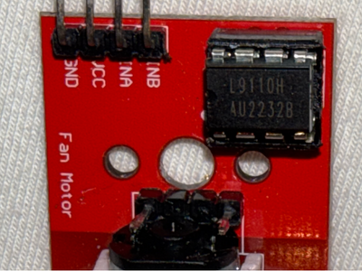
To get started with controlling a motor using the ESP32 and L9110 motor driver, you’ll need a few essential components. Each plays a specific role in the setup, allowing you to control the motor’s speed and direction effectively.
1. ESP32 Development Board
📦 Wemos D1 Mini (ESP8266) Development Board
2. L9110 Motor Driver
📦 L9110 Motor Driver
3. DC Motor
📦 DC Motor
4. Jumper Wires
📦 Jumper wires
5. Breadboard (Optional)
📦 Breadboard
Alternative - L9110 Fan Motor Module
📦 Fan Motor Module based on L9110 driver
Step-by-Step Guide to Connecting ESP32 to L9110 #
In this section, we'll go over the wiring instructions for connecting your ESP32 to the L9110 motor driver. This setup will enable you to control a DC motor's direction and speed using simple code.
Wiring Instructions #
Follow these steps to wire your components together:
Connect ESP32 to L9110 Inputs
- ESP32 Pin 1 → L9110 IN1: This connection controls one direction of the motor.
- ESP32 Pin 4 → L9110 IN2: This connection controls the opposite direction of the motor.
Connect Motor to L9110 Motor Output Pins
- Motor Terminal 1 → L9110 Motor A Output (A-OUT1)
- Motor Terminal 2 → L9110 Motor A Output (A-OUT2)
- These connections allow the L9110 to control the motor's rotation direction.
Power Connections
- L9110 GND → ESP32 GND: Connect the ground pin of the L9110 to the ESP32 ground.
- L9110 VCC (Power) → Motor Power Supply: Connect VCC on the L9110 to an appropriate external power source for the motor (e.g., 5-12V). This external power source provides the necessary current for the motor without overloading the ESP32.
Optional: Power ESP32 from the Same Source
- If you’d like to power the ESP32 from the same power source as the motor, you can use a 5V regulator to connect the power supply’s output to the ESP32’s 5V input pin.
- Note: Be cautious of voltage differences to avoid damaging your ESP32. Ensure that the motor’s power supply voltage matches the ESP32’s input requirements if using a shared source.
Diagram of the Setup #
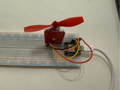
Here’s a simple layout for your reference:
- ESP32 Pin 1 → L9110 IN1
- ESP32 Pin 4 → L9110 IN2
- Motor Terminal 1 → L9110 A-OUT1
- Motor Terminal 2 → L9110 A-OUT2
- L9110 GND → ESP32 GND
- L9110 VCC → External Motor Power Supply (5-12V)
This setup allows the ESP32 to control the motor's direction by sending signals to IN1 and IN2 pins of the L9110, while the motor’s external power supply provides the required current to drive the motor.
Final Check #
Once everything is connected:
- Verify that all connections are secure.
- Double-check that the ground (GND) connections are linked properly across the ESP32, L9110, and the motor's power supply.
- Ensure that your external power supply matches the motor’s voltage requirements.
Coding to Control Motor Direction and Speed #
Once you've set up your wiring, the next step is to program the ESP32 to control the motor's direction and speed using the Arduino IDE. In this section, we'll go through a simple code example that shows how to set motor pins, control direction, and stop the motor.
The code we'll use controls the motor in three states:
- Forward: Moves the motor in one direction.
- Reverse: Moves the motor in the opposite direction.
- Stop: Stops the motor.
By defining motor control pins and setting up Pulse Width Modulation (PWM), we can control both the direction and speed of the motor. PWM allows us to vary the speed of the motor by sending a signal that alternates between HIGH and LOW states at a set frequency.
Code Example #
Here’s the complete code to control the motor's direction and speed:
// Pins connected to L9110H Motor Driver
#define A_IN1 1  // Motor A INA
#define A_IN2 4  // Motor A INB

// Speed of the motor (PWM)
int motorSpeed = 128; // Range: 0 to 255

void setup() {
  // Set the pins as outputs
  pinMode(A_IN1, OUTPUT);
  pinMode(A_IN2, OUTPUT);

  Serial.begin(115200);
  Serial.println("ESP32 L9110H Motor Driver Example");
}

void loop() {
  // Forward direction
  Serial.println("Moving Forward");
  analogWrite(A_IN1, motorSpeed); // Set IN1 to PWM speed
  analogWrite(A_IN2, 0);          // IN2 set to LOW
  delay(2000);                    // Move forward for 2 seconds

  // Stop
  Serial.println("Stopping");
  analogWrite(A_IN1, 0);
  analogWrite(A_IN2, 0);
  delay(1000);                    // Stop for 1 second

  // Reverse direction
  Serial.println("Moving Reverse");
  analogWrite(A_IN1, 0);          // IN1 set to LOW
  analogWrite(A_IN2, motorSpeed); // Set IN2 to PWM speed
  delay(2000);                    // Move reverse for 2 seconds

  // Stop
  Serial.println("Stopping");
  analogWrite(A_IN1, 0);
  analogWrite(A_IN2, 0);
  delay(1000);                    // Stop for 1 second
}
This code controls the direction and speed of a DC motor using the ESP32 and the L9110H motor driver. Here’s a brief explanation of each part:
Pin Definitions
#define A_IN1 1and#define A_IN2 4: The ESP32 pins connected to the L9110H motor driver’s input pins (INA and INB) for controlling motor direction.
Motor Speed
int motorSpeed = 128;: Sets the motor’s speed using PWM, where values range from 0 (off) to 255 (full speed).
Setup Function
pinMode(A_IN1, OUTPUT);andpinMode(A_IN2, OUTPUT);: Sets the motor control pins as outputs.Serial.begin(115200);: Starts the serial monitor for debugging.
Loop Function
- Forward Movement:
analogWrite(A_IN1, motorSpeed);setsA_IN1to the specified PWM speed, whileanalogWrite(A_IN2, 0);keepsA_IN2low, causing the motor to move forward.delay(2000);holds this state for 2 seconds.
- Stop:
analogWrite(A_IN1, 0);andanalogWrite(A_IN2, 0);stop the motor by setting both inputs to zero.delay(1000);holds the stop position for 1 second.
- Reverse Movement:
analogWrite(A_IN1, 0);andanalogWrite(A_IN2, motorSpeed);setA_IN2to the PWM speed whileA_IN1is low, moving the motor in reverse.delay(2000);holds the reverse state for 2 seconds.
- Stop Again:
- Sets both pins to zero to stop the motor, with a delay of 1 second before repeating the loop.
- Forward Movement:
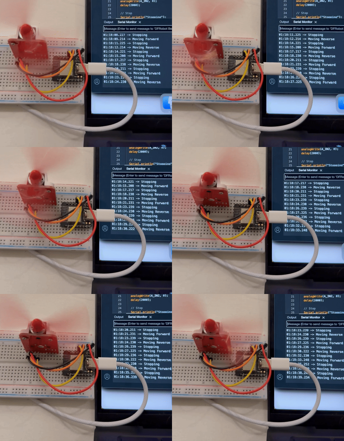
This code loops continuously, making the motor move forward, stop, reverse, and stop again.
Conclusion #
In this guide, we covered how to set up, code, and control a DC motor using an ESP32 and the L9110 motor driver. We started with the essential components needed for motor control, followed by clear wiring instructions to connect the ESP32 and the L9110. Next, we explored a straightforward code example in the Arduino IDE, which allows you to control the motor’s direction and speed with PWM.
With this foundation, you now have the skills to incorporate motor control into a wide range of projects. If you’re building a simple robot, an automated device, or an IoT project, understanding motor control with the ESP32 and L9110 opens up many possibilities.


