
Powering ESP32 with 12V Power Source using Buck Converter
Safely power an ESP32 from a 12V source using a buck converter. Discover buck (step-down) converter modules, wiring diagrams, voltage adjustment, and safety tips.
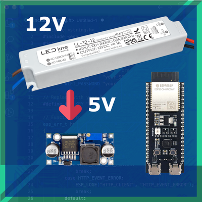
In case you want your project to have only a single 12V power source, for example running 12V LED strips alongside an ESP32 or powering an ESP32 directly from a car's 12V battery, you need a way to step the voltage down. Since ESP32 development boards operate at 3.3V logic and typically require 5V input for stable operation, directly connecting 12V would result in irreversible damage. Proper voltage regulation ensures safety and reliable power delivery to the ESP32.
⬇️ Jump to ESP32 with Buck (Step-Down) Converter Wiring
Common Use Cases #
Some scenarios where you might need to power an ESP32 from a 12V source include:
- Car electronics – ESP32-based IoT dashboards, GPS trackers, or smart vehicle monitoring systems powered directly by a 12V car battery.
- 12V LED power strips – Controlling addressable or analog LED strips where a single power source is preferred for both the LEDs and the ESP32.
- Pumps and relays – Many automation projects involve 12V solenoid valves, motors, or relays, and using a single 12V power source simplifies wiring.
Since the ESP32 cannot handle 12V directly, a proper voltage regulation method is necessary. In this guide, we will explore the best ways to step down 12V safely and efficiently to power your ESP32.
🔗 If your project involves LED strips, check out this guide on addressable LED strips.
🔗 For a comparison of different ESP32 boards, visit this list of ESP32 development boards.
Why Direct Connection is Not an Option #
Powering an ESP32 directly from a 12V source is not an option due to its operating voltage limitations and the risk of permanent damage. Here’s why:
The ESP32 operates at 3.3V logic but development boards typically requires 5V on the Vin pin to function properly. The development boards usually have a built-in voltage regulator and takes 5V from USB or Vin and steps it down to 3.3V for the microcontroller.
A voltage regulator ensures that the ESP32 receives a stable 3.3V supply without dangerous fluctuations. Power instability can cause random resets, crashes, and even permanent failure.
| Pin | Expected Voltage |
|---|---|
| 3.3V | 3.3V (regulated output) |
| Vin | 5V (regulated input) |
| USB | 5V |
Why 12V Direct Connection is Dangerous #
Some ESP32 development boards claim to support 5-12V input on the Vin pin due to their onboard voltage regulators. However, powering them directly from a 12V source is still not a good idea. Here’s why:
Overheating & Inefficiency: Most ESP32 boards use linear voltage regulators to step down 12V to 3.3V. These regulators convert excess voltage into heat, which can cause overheating, instability, and reduced lifespan of the board.
Regulator Load Limitations: Even if the voltage regulator can technically accept 12V input, it might not handle high current loads efficiently. If your ESP32 is running Wi-Fi, sensors, or external peripherals, the regulator might struggle to supply stable power.
Voltage Drop at High Current: Many onboard regulators don’t have enough headroom to handle a 12V input under load. As the ESP32 draws more current (e.g., during Wi-Fi transmissions), the regulator may not be able to maintain a steady 3.3V output.
Component Stress & Failure Risks: Running the regulator at its maximum rated voltage (e.g., 12V) continuously puts excessive stress on it. This can lead to early component failure, causing unpredictable resets, instability, or even permanent damage.
Does Your ESP32 Board Have a Built-in Voltage Regulator? #
ℹ️ Most ESP32 development boards include an onboard voltage regulator that steps down 5V to 3.3V, but not all boards have the same regulator specs! Some boards claim to support higher input voltages (e.g., 6V-12V on Vin), but this depends entirely on the regulator used.
You should always check your board’s datasheet or look up detailed specifications here:
🔗 Explore All ESP32 Development Boards
Safe Powering Options #
Instead of direct connection, consider using a buck converter (step-down regulator) to safely bring 12V down to 5V before connecting to Vin. More details on this in the next section!
🔗 You might also be interested in optimizing power consumption for low-power applications: Deep Sleep & Low Power Optimization on ESP32
Not all voltages are safe to supply directly to an ESP32 board, even if some boards claim to support higher input ranges. The Vin pin is usually connected to a 5V to 3.3V regulator, and feeding the wrong voltage can cause overheating, instability, or instant failure.
Here's a breakdown of different voltages and their effects on the ESP32:
[24V] --> [ESP32 Vin] ❌ Instant failure! Most onboard regulators are NOT rated for this voltage.
[12V] --> [ESP32 Vin] ⚠️ High heat & inefficiency! Some boards claim support, but long-term use is risky.
[7V]  --> [ESP32 Vin] ⚠️ May work, but still generates unnecessary heat. Better to use 5V.
[5V]  --> [ESP32 Vin] ✅ Recommended! Direct and safe for most ESP32 boards.
[3.3V] --> [ESP32 3.3V] ✅ Safe, but bypasses the regulator—ensure stable power!
[12V] --> [5V Step-down Regulator] --> [ESP32 Vin] ✅ Best practice! Efficient conversion for stable operation.
Best Solution: Buck Converter (Step-Down Voltage Regulator) #
When powering an ESP32 from a 12V source, the best approach is to use a buck converter (also called a step-down switching regulator). Unlike linear regulators, which dissipate excess voltage as heat, buck converters efficiently convert higher voltages to lower voltages with minimal energy loss.
What is a Buck Converter? #
A buck converter is a DC-DC switching regulator that reduces input voltage while maintaining efficiency. It works by rapidly switching the input voltage on and off, storing energy in an inductor, and then smoothing it into a stable lower voltage.
Here’s a simplified breakdown:
- High-frequency switching: The circuit rapidly turns the input voltage on and off using a MOSFET.
- Inductor stores energy: Each time the switch is on, energy builds up in an inductor.
- Controlled release: The stored energy is gradually released when the switch turns off, creating a lower, stable output voltage.
- Smoothing capacitor: A capacitor at the output reduces ripple, providing a clean 5V or other voltage output.
Why Choose a Buck Converter Over a Linear Regulator? #
You might have heard of linear voltage regulators like the AMS1117-3.3V or 7805, which are commonly used to step down voltage. While they are simple to use and don’t require additional circuitry, they come with a major drawback — they convert excess voltage into heat. This makes them extremely inefficient.
On the other hand, a buck converter (switching regulator) efficiently steps down voltage without wasting energy as heat, making it a much better option for power-sensitive applications.
Here’s a comparison of both:
| Feature: | Buck Converter ✅ | Linear Regulator ❌ |
|---|---|---|
| Efficiency | 80-95% (very efficient) | 40-60% (wastes energy as heat) |
| Heat Output | Low (minimal heat) | High (excess heat loss) |
| High Voltage Support | Works with 12V, 24V, or higher | Struggles above 7V |
| Current Handling | Can provide higher current (2A+) | Limited to low current (<1A) |
| Ideal For | Battery-powered & heat-sensitive applications | Only when input is close to output (e.g., 5V → 3.3V) |
💡 If you’re dropping from 12V to 5V, a buck converter is the way to go! It avoids heat buildup, reduces power loss, and keeps your ESP32 stable.
Buck Converter Step-Down Modules with Integrated 5V Output #


These modules are excellent for powering ESP32 boards from batteries or higher-voltage power sources.
| Buck Converter | Voltage Range | Max Current | Efficiency | Size |
|---|---|---|---|---|
| LM2596 | 4V - 40V | 3A | ~75-80% | Larger |
| MP1584 | 4.5V - 28V | 2A | ~85-90% | Compact |
| Mini360 5V | 5 - 30V | 1.8A | ~90-95% | Mini |
Adjustable vs. Fixed Voltage Regulators and Current Considerations #
Buck converters come in two main types: adjustable and fixed voltage regulators. Adjustable regulators, like the LM2596, allow fine-tuning of the output voltage via a potentiometer, making them versatile for different applications. However, they require manual adjustment, and any accidental misconfiguration could damage the ESP32. Fixed regulators, on the other hand, provide a stable 5V output, eliminating the risk of overvoltage. Since the ESP32 operates reliably at 5V on the Vin pin, a fixed 5V converter is often the safest and most convenient choice.
Current rating is another important factor when selecting a buck converter. The ESP32 itself typically consumes 100-300mA, but the total power demand increases when adding components like displays, sensors, and relays. A 1A regulator is generally sufficient for basic ESP32 projects, but for setups with multiple peripherals, a 2A or 3A converter is recommended to ensure stable performance. Choosing a regulator with some extra current capacity helps prevent voltage drops and ensures reliable operation.
Wiring a Buck Converter to an ESP32 #
If you're using a 12V power source and need to power an ESP32, a buck converter (step-down voltage regulator) is the safest and most efficient way to convert 12V down to 5V. Many ESP32 development boards, such as those listed in the ESP32 development board guide, have a Vin pin that accepts 5V, making this an easy setup.
Connect the 12V Input to the Buck Converter
- Identify the input terminals on the buck converter (IN+ and IN-).
- Connect IN+ to the positive terminal of the 12V power supply.
- Connect IN- to the ground (GND) of the power supply.
Adjust the Output Voltage to 5V
- If using an adjustable buck converter (such as LM2596 or MP1584), follow these steps:
- Use a multimeter to measure the output voltage between OUT+ and OUT-.
- Turn the adjustment potentiometer (small screw on the module) until the output reads 5V.
- If using a fixed 5V regulator, such as Mini360 5V, no adjustment is necessary.
- If using an adjustable buck converter (such as LM2596 or MP1584), follow these steps:
Connect the Buck Converter Output to the ESP32
- Connect the OUT+ (5V) of the buck converter to the Vin pin on the ESP32.
- Connect the OUT- (GND) of the buck converter to the GND pin on the ESP32.
Wiring Diagram #

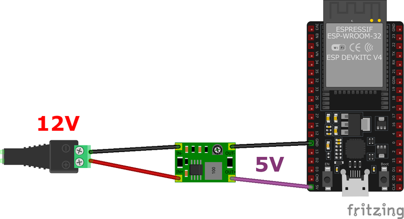
| Component | Buck Converter Pin | ESP32 Pin |
|---|---|---|
| 12V Power (+) | IN+ | N/A |
| 12V Power (GND) | IN- | N/A |
| Buck 5V Output | OUT+ | Vin |
| Buck GND Output | OUT- | GND |
Important Notes #
- Most ESP32 boards, including ESP32 DevKit V1, have a voltage regulator on Vin, allowing safe operation with 5V input.
- Generaly avoid exceeding 5.5V on the Vin pin, as it may damage the onboard regulator.
- Ensure your buck converter can supply at least 1A or more, if additional peripherals (e.g., sensors, displays) are connected.
Summary #
Powering an ESP32 from a 12V source is best done using a buck converter, which ensures efficient and stable 5V output. Adjustable regulators like the LM2596 and MP1584 allow fine-tuning, while fixed 5V models offer reliability. Proper wiring involves connecting the 12V source to the converter’s input, adjusting the output if necessary, and supplying the ESP32’s Vin and GND with 5V.
Measuring the voltage before connecting ensures the ESP32 isn’t exposed to overvoltage, which could damage its internal regulator. Compared to linear regulators, buck converters provide higher efficiency, reducing heat and extending battery life in portable applications.