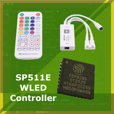
$8 SP511E ESP8265 - Transform Your LED Controller with WLED
Unlock the full potential of the SP511E LED controller with WLED. Flash custom firmware to the 8$ Addressable LED Strip Controller with WiFi, IR Remote and More
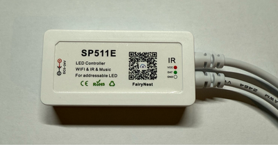
The SP511E and SP501E are popular and affordable WiFi addressable LED strip controllers that allows wireless control of led strips such as WS2812B, SK6812 or other. You can check the full list in the Addressable LED Strips post. The SP511E, is a successor and improved version of the SP501E, which comes with added features like an IR receiver for remote control, making it even more versatile.
Supporting LED strips with voltage ranges from 5V to 24V, the SP511E provides a range of control options: WiFi, Bluetooth, IR remote, and even a built-in microphone for sound-reactive lighting.
By default, the SP511E comes with the FairyNest firmware, which provides 180 dynamic effects. However, many of these are simply variations in color combinations for a limited number of animations. Additionally, FairyNest requires you to register with your email before you can even start using the app and who wants that...
But that's not a problem in our case, because the SP511E (And SP501E) is powered by the ESP8285 microcontroller. This ESP-based architecture allows to easily install an open-source WiFi LED Controller software, such as WLED.
Dissasambling the SP511e #
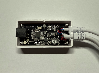
The SP511e controller opens easily, in the same way as other similar controllers. On the side of the controller's case, check for the small release hole. You can insert a tool like a paperclip or a small pin into this hole to gently pop the bottom cover off.
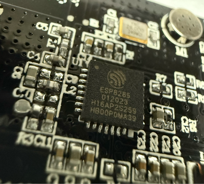
Carefully remove the PCB board, ensuring nothing is damaged in the process, especially the plastic box. Once it's out, take a moment to locate the microcontroller among the various components. It doesn't take long to spot the chip featuring the distinctive Espressif logo. And on closer inspection, it says the ESP8265, just as we expected.
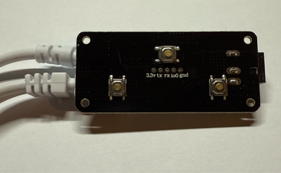
If you flip the board over, you'll notice a set of pins conveniently located in the center of the board. Well that's convinient! Even better, the pins are clearly labeled, making it easy to identify their functions! These pins are exactly what we need to flash the WLED on the ESP8265 microcontroller.
Intercepting the Exposed SP511e Pins #
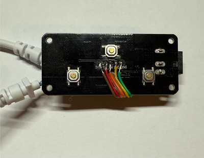
I’ve soldered some wires onto the exposed pins for a more secure and reliable connection. With the wires in place, it’ll be much easier to proceed with flashing the WLED firmware.
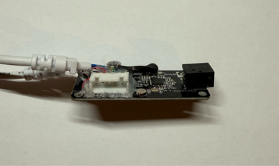
I’ve also added a Micro JST connector on the other side of the board. While this connector is purely optional, I figured it would make things much easier for the initial debugging process. By using the connector, I can quickly connect and disconnect components or devices without risking damage to the soldered wires.
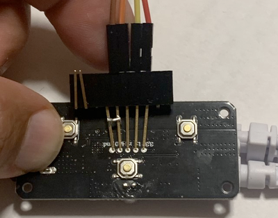
If you’d prefer to avoid soldering or anticipate programming multiple boards in the future, you can consider building a pogo pin clip, as recommended in this guide. This approach offers a non-permanent, reusable connection method that’s especially useful for programming several boards without the need for repeated soldering. (Image from scottrbailey GitHub).
Connecting the ESP8265 with USB-to-UART #
Now that we have access to the pins, the next step is to connect the ESP8265 microcontroller to a computer. To do this, you’ll need a USB-to-UART controller which acts as a bridge between the microcontroller and your computer. A popular choice for this purpose is the FTDI chip, known for its reliability and ease of use.
Connect the wires from SP511e to the FTDI as following:
| SP511E Pin | FTDI Pin |
|---|---|
| GND | GND |
| 3.3V | 3.3V |
| TX | TX |
| RX | RX |
| GPIO0 | GND |
You might think I mixed the TX, RX Connection, but at least on my controller it seems the manufacturer went with a mindset of "This connects to...". Oh well...
In case it is not working for you, try switching the connection to default TX (SP511e) -> RX (FTDI), RX (SP511e) -> TX (FTDI)
Some of the FTDI programmers have 5V and 3.3V power pins. Make sure to use the 3.3V!
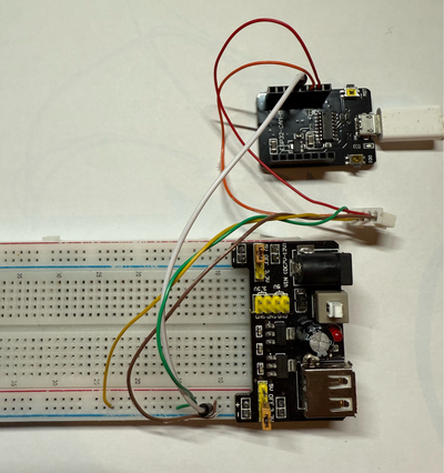
However, in my case... I couldn't find any FTDI programmer laying around, but I had the ESP-CAM-MB by hand, so using the instructions here I came up with this contraption. Since the ESP-CAM-MB doesn’t directly provide the necessary power, I had to use an external power source to drive the setup. As a result, the final contraption looks a bit messy due to the extra wires and components involved.
Your setup with an FTDI programmer should look much neater and more straightforward. If you can find an FTDI programmer, I highly recommend using it for a cleaner and more manageable configuration.
Flashing the WLED to SP511e #
- Download WLED Binary
Go to WLED Releases on GitHub.
According to WLED installation instructions, the WLED_0.x.x_ESP01.bin is suitable for the ESP8265.
Download the latest version with ESP01.bin - in our case WLED_0.15.0-rc1_ESP02.bin.
- Flash with the Esptool
Follow the instructions here to install the Esptool and flash the WLED binary onto your ESP8265.
In our case, since we already have the Esptool installed, we run the following command to flash the binary:
esptool.py write_flash 0x0 ./WLED_0.15.0-rc1_ESP01.binAnd we get the following output. (Note it might take a while to upload the code):
esptool.py v4.8.1
Found 1 serial ports
Serial port /dev/cu.usbserial-210
Connecting....
Detecting chip type... Unsupported detection protocol, switching and trying again...
Connecting...
Detecting chip type... ESP8266
Chip is ESP8285H16
Features: WiFi, Embedded Flash
Crystal is 26MHz
MAC: d8:bc:38:8d:1b:0f
Uploading stub...
Running stub...
Stub running...
Configuring flash size...
Flash will be erased from 0x00010000 to 0x000e5fff...
Compressed 876016 bytes to 632261...
Wrote 876016 bytes (632261 compressed) at 0x00010000 in 61.1 seconds (effective 114.6 kbit/s)...
Hash of data verified.

Leaving...
Hard resetting via RTS pin...
Testing the WLED on SP511e #
- Disconnect the controller from FTDI
The WLED flashing is completed, you can disconnect the FTDI.
- Connect the controller using the main power
Using a 5 to 24V power supply, connect the SP511e controller as you normally would. Make sure the FTDI is disconnected to avoid supplying power from both FTDI and external power suply!
- Connect to WLED WiFi Access Point
Wait a few minutes and Check the WiFi settings with your computer or phone - shortly the WiFi network Called “WLED-AP” should appear. Connect to this WiFi network, when prompted for password, enter wled1234.
- Access the WLED Control Panel
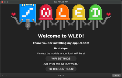
After connecting to the WLED AP, the pop-up should appear with the WLED Web Control. In case the popup doesn't appear, in the browser go to http://4.3.2.1/.
Configuring WLED #
Once you’ve successfully flashed the WLED firmware onto your ESP8265, the next step is to configure it to according to the SP511e pinout. WLED offers a wide range of customization options, allowing you to tailor everything from WiFi connectivity to advanced features like IR remotes and microphones. Below, we’ll guide you through the essential configuration steps to get your SP511e functionality up and running with the WLED.
WiFi Settings #
To connect your ESP8265 running WLED to your WiFi network, follow these steps:
Open the WiFi Settings Menu
- Click on the "WIFI SETTINGS" option in the WLED web interface to access the configuration page for network settings.
Scan for Available Networks
- Click the "Scan" button to display a list of available WiFi networks in your area. This helps you quickly find your WiFi without manually entering the network details.
Select Your WiFi Network
- From the dropdown list that appears, select your WiFi name (SSID). This ensures you connect the ESP8265 to the correct network.
Enter Your WiFi Password
- Enter the password for your WiFi network in the provided field. Make sure to double-check the password to avoid connection errors.
Save and Connect
- Click "Save & Connect" to save the settings. The ESP8265 will restart automatically and attempt to connect to the WiFi network using the provided credentials.
Find the Device’s New IP Address
- Once the ESP8265 has connected to the network, it will be assigned a new IP address by your router. You can locate this IP address by checking your router’s device list or using a network scanning tool.
- If you prefer a quick command-line method, run an ARP scan on your network to identify the new device. Use the following command:
arp -a- Look for an unfamiliar or new IP address in the list of connected devices. In our example, the ESP8265 was assigned the IP address:
192.168.129.26.
Configure LEDs #
To set up your addressable LED strip with WLED, follow these steps:
- Connect Your LED Strip
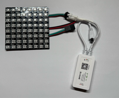
Go ahead and connect your preferred addressable LED strip. For our testing, we use a WS2812b 8x8 matrix, but you can connect any compatible LED strip. We use WS2812b 8x8 matrix for testing so simply connect it like this:
- Access WLED Web Portal
- Open the WLED web interface - in the browser, go to the IP of newly connected WLED -
http://192.168.129.26/in our case.
- Open the WLED web interface - in the browser, go to the IP of newly connected WLED -
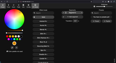
You will see the default wled control panel. However if you try to select anything, the LEDs will most likely not work yet… We need to configure the data pin.
Open LED Configuration Screen
- Navigate to the Config -> LED Preferences section in the settings menu.
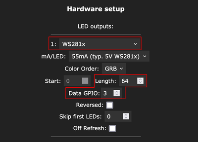
Set Up the LED Parameters
- LED Type: Select the appropriate LED type for your strip, such as WS2812b.
- Number of LEDs: Enter the total number of LEDs in your strip or matrix. For a WS2812b 8x8 matrix, that we use, this is
64. - Data Pin: Specify the GPIO pin connected to the data line of your LED strip - GPIO number
3in SP511e case.
- Save and Test
- Click Save to apply your settings.
- Test the LEDs by turning them on via the WLED interface and observing their behavior. You can try different effects and colors to ensure everything is working correctly.
Configuring buttons #
The SP511E board features three buttons with the following GPIO mappings:
- GPIO2 - PWR button: Typically used to turn the lights on or off.
- GPIO13 - M Button: Default behavior is to cycle through lighting modes.
- GPIO14 - S Button: Designed for additional actions, such as scene selection.
However, the WLED binary from GitHub we installed only supports two GPIOs for button configurations on the ESP8265 by default. If you wish to configure all three buttons, you would need to manually compile WLED and include the build flag -D WLED_MAX_BUTTONS=5 (or up to 10 buttons). But that is for another time.
Open LED Preferences
- Again, Navigate to the WLED web interface and click "Config", then select "LED Preferences" from the menu.
Set GPIO Pins for Buttons
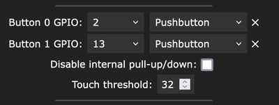
- Scroll down until you see the GPIO buttons settings. Assign actions to the available buttons as follows:
- Button 0 -> Pin 2 - Pushbytton: Configure this for the PWR button, which handles the default Turn On/Off action.
- Button 1 -> Pin 13 - Pushbutton: Assign this to the M Button for the default Select Mode action.
- Scroll down until you see the GPIO buttons settings. Assign actions to the available buttons as follows:
- Test Button Behavior
- After saving the configuration, try clicking the Power and M buttons on the SP511E board. Verify that the PWR button toggles the lights and that the M button cycles through the available lighting modes. This behaviour should be by default with the correct setup.
Configuring IR Remote #
To configure the IR remote for the SP511E controller, follow these steps:
Set the IR Pin
- In the WLED interface, LED Preferences, scroll down to the IR settings and ssign the IR pin to GPIO5, which is the designated IR input pin on the SP511E.
Set the Remote Type
- Select "JSON remote" as the remote type.
Upload the Configuration File
- Once you select "JSON remote", an option to upload the configuration file will appear.
- Download the 38-key configuration file compatible with SP511E controllers from the following link:
38-key_ir.json. - Select this file and click "Upload" in the WLED interface.
Save Your Settings
- After the file has been uploaded successfully, click "Save" at the top of the screen to finalize the IR configuration.
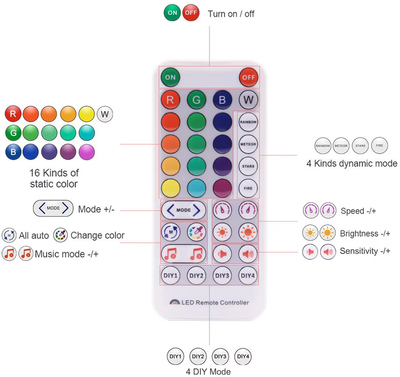
With this setup, the 38-key IR remote that comes together with the SP511e Controller should be fully functional, allowing you to control your WLED setup with the IR remote.
Configuring Microphone #
Currently, I am unsure about the ESP8265's ability to handle the WLED Sound Reactive features. The ESP8265 is a relatively modest microcontroller, and I dont think it will have enough processing power to handle real-time sound analysis and lighting effects from WLED. However, I will further investigate this and will update this post accordingly later.
SP511e ESP8265 Pinout #
While SP511e offers a variety of GPIOs for different functionalities, such as IR, buttons or microphone, it is not very easy to identify the GPIO pins. Here are the SP511e GPIO Pinout Mappings we have discussed earlier, in one place:
Known GPIO Functions #
- GPIO3: Main WLED output.
- GPIO5: IR input.
- GPIO2: Power Button.
- GPIO13: M Button.
- GPIO14: S Button
According to divsys on the WLED Discourse forum, here is an overview of the known GPIO functions, additional features, and considerations for advanced configurations, including options for multiple LED strips, IR input, and microphone support.
Additional Information #
- TOUT (ADC): Mic input for sound-reactive features.
- GPIO1 (TX Pin): Accessible through a 100Ω resistor (R8). This pin could be used for a second LED strip, configured at the TX pad.
- GPIO15: Pulldown with a 10kΩ resistor (R4). This pin could serve as a third LED strip output, accessible at R4 (located toward the bottom of the board). Soldering this requires precision and delicate handling.
- Both GPIO1 and GPIO15 may require a level shifter for a usable output. Initial tests confirm signal output when configured for a second or third strip, though functionality without a level shifter remains limited.
Other GPIOs #
GPIO0, GPIO6, GPIO7, GPIO8, GPIO10, GPIO11:
These pins are present on the ESP8265 chip but lack accessible pads or traces on the SP511E board. Accessing them would require very fine soldering directly on the chip, which is generally impractical for most users.GPIO4, GPIO9:
On some SP511E boards, these pins appear to be physically broken off the ESP8265 chip, rendering them unusable.
Conclusion #
In this guide, we’ve walked through the process of configuring and customizing the SP511E ESP8265 controller to work with WLED. From identifying the microcontroller and connecting pins, to flashing the firmware, configuring LEDs, and exploring button and microphone functionality, you now have the tools and knowledge to make the most of this powerful yet compact device.
The SP511E offers great flexibility for addressable LED setups, with accessible GPIOs for essential features and potential for advanced configurations like multiple LED strips and sound-reactive effects. While the ESP8265 has some limitations, its compatibility with WLED makes it a great choice for DIY lighting projects.

