
ESP32-S3 Super Mini
Compact ESP32-S3 board with Wi-Fi, BLE, and AI support - great for smart, space-saving IoT and edge AI applications.

Pinout
37 pins · 2.54 mm pitch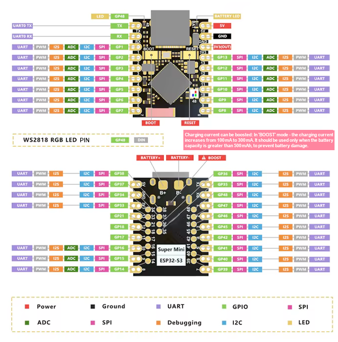
| Pin | GPIO | Labels | Status | Capabilities | Notes |
|---|---|---|---|---|---|
| 1 | - | 5V | power | - | 5V power input for the board |
| 2 | - | GND | ground | - | Ground connection |
| 3 | - | 3V33.3V | power | - | 3.3V power output for peripherals |
| 4 | - | TX | uart | uart | TX |
| 5 | - | RX | uart | uart | RX |
| 6 | 1 | IO1GP1 | safe | adc | GPIO, ADC Pin |
| 7 | 2 | IO2GP2 | safe | adc | GPIO, ADC pin |
| 8 | 3 | IO3GP3 | strapping | adc | GPIO, ADC pin |
| 9 | 4 | IO4GP4 | safe | adc | GPIO, ADC pin |
| 10 | 5 | IO5GP5 | safe | adc | GPIO, ADC pin |
| 11 | 6 | IO6GP6 | safe | adc | GPIO, ADC pin |
| 12 | 7 | IO7GP7 | safe | adc | GPIO, ADC pin |
| 13 | 8 | IO8GP8 | safe | adc | GPIO, ADC pin |
| 14 | 9 | IO9GP9 | strapping | adc | GPIO, ADC pin |
| 15 | 10 | IO10GP10 | strapping | adc | GPIO, ADC pin |
| 16 | 11 | IO11GP11 | strapping | adc | GPIO, ADC pin |
| 17 | 12 | IO12GP12 | strapping | adc | GPIO, ADC pin |
| 18 | 13 | IO13GP13 | strapping | adc | GPIO, ADC pin |
| 19 | 14 | IO14GP14 | strapping | adc | GPIO, ADC pin |
| 20 | 15 | IO15GP15 | safe | adc | GPIO, ADC pin |
| 21 | 16 | IO16GP16 | safe | adc | GPIO, ADC pin |
| 22 | 17 | IO17GP17 | safe | - | GPIO |
| 23 | 18 | IO18GP18 | safe | - | GPIO |
| 24 | 21 | IO21GP21 | safe | - | GPIO |
| 25 | 33 | IO33GP33 | strapping | - | GPIO |
| 26 | 34 | IO34GP34 | strapping | - | GPIO |
| 27 | 35 | IO35GP35 | strapping | - | GPIO |
| 28 | 36 | IO36GP36 | strapping | - | GPIO |
| 29 | 37 | IO37GP37 | strapping | - | GPIO |
| 30 | 38 | IO38GP38 | strapping | - | GPIO |
| 31 | 39 | IO39GP39 | strapping | - | GPIO |
| 32 | 40 | IO40GP40 | strapping | - | GPIO |
| 33 | 41 | IO41GP41 | strapping | - | GPIO |
| 34 | 45 | IO45GP45 | strapping | - | GPIO |
| 35 | 46 | IO46GP46 | strapping | - | GPIO |
| 36 | 47 | IO47GP47 | strapping | - | GPIO |
| 37 | 48 | IO48GP48 | strapping | - | GPIO |
Start with these
12 pins with no boot or system involvementFreely assignable - no strapping, flash, USB or JTAG duties. Ideal first picks for buttons, sensors and LEDs.
Fine - with a little care
sampled at boot or shared with debug/serial| Pin | Label | What to know | Role |
|---|---|---|---|
| IO3 | GPIO3 | Sampled at reset to select JTAG interface (USB Serial/JTAG controller vs. external pins). Improper use can disable external JTAG or alter debug interface. | Strapping |
| IO39 | MTCK (GPIO39) | Default JTAG debugging TCK pin. If JTAG is needed, this pin must be free; it may also be used internally for PSRAM chip select on certain modules, so avoid repurposing it. | Other |
| IO40 | MTDO (GPIO40) | Default JTAG TDO output for debugging. Using it as GPIO will interfere with JTAG debugging functionality. | Other |
| IO41 | MTDI (GPIO41) | Default JTAG TDI input for debugging. Should be reserved for JTAG or left unused if JTAG is to remain available. | Other |
| IO45 | GPIO45 | Determines flash/PSRAM power voltage (3.3 V vs 1.8 V) at boot. Must match hardware configuration; using as GPIO can upset flash supply setting. | Strapping |
| IO46 | GPIO46 | Must be at a defined level during reset (with GPIO0) to select normal or download boot and UART/USB print mode. This pin is input-only (no output drive), so it should be left for its intended strapping function. | Strapping |
Only if you know the tricks
wired to flash or USB - expect a fight| Pin | Label | What to know | Role |
|---|---|---|---|
| IO9 | FSPIHD | Connected to external flash (data/hold signal) on most modules. Not recommended for use as GPIO, since it must remain dedicated to flash communication. | Flash |
| IO10 | FSPICS0 | Used to select the external flash chip. It is required for flash access and cannot be repurposed without losing flash connectivity | Flash |
| IO11 | FSPID | Used as a data line for flash (and in-package PSRAM). It should not be used as GPIO when the flash/PSRAM is in use. | Flash |
| IO12 | FSPICLK | Drives the flash (and PSRAM) clock. This critical signal must be reserved for memory and not used as general GPIO. | Flash |
| IO13 | FSPIQ | Used as a data line for flash/PSRAM transfers. Not available for other uses when flash/PSRAM is connected. | Flash |
| IO14 | FSPIWP | Connected to external flash (data/write-protect signal). Not recommended as GPIO because it’s reserved for flash operations. | Flash |
| IO33 | FSPIHD | On chips/modules with integrated flash, this IO is wired to the flash hold pin internally. It cannot be reassigned to GPIO without breaking flash access. | Flash |
| IO34 | FSPICS0 | Wired to the chip select of the internal flash in flash-equipped variants. It must remain low during flash operation, so it’s not available for other use. | Flash |
| IO35 | FSPID / PSRAM_D0 | In modules with octal PSRAM, this pin is connected to the PSRAM data line. It is reserved for memory interface and not free for general GPIO when flash/PSRAM is present. | Flash |
| IO36 | FSPICLK / PSRAM_CLK | In modules with octal PSRAM, this pin drives the PSRAM clock. It must be dedicated to the memory interface, not used as a regular GPIO when that interface is in use. | Flash |
| IO37 | FSPIQ / PSRAM_DQS | In modules with octal PSRAM, this pin is connected to the PSRAM’s DQS signal. It cannot be repurposed without disrupting the PSRAM/flash communication. | Flash |
| IO38 | FSPIWP | On flash-equipped chips, this pin is tied to the flash’s WP# (or D3) line. It should be avoided for other use, as it’s needed for flash operations. | Flash |
| IO47 | SPICLK_P | Used only on variants with Octal SPI interface (e.g. ESP32-S3R16V) as part of the differential clock pair. On such chips it operates at 1.8 V and is reserved for the high-speed octal SPI clock, not for general GPIO use. | Flash |
| IO48 | SPICLK_N | Used only on variants with Octal SPI interface, as the negative leg of the differential clock&. On such chips it operates at 1.8 V; it should be avoided for GPIO to prevent conflicts with the octal flash/PSRAM clock. | Flash |
Pinout notes Across 37 pins (2.54 mm pitch), the ESP32-S3 Super Mini exposes 32 GPIO plus 5V , GND and 3V3 for power. On the analog side there are 16 ADC-capable pins for…
Across 37 pins (2.54 mm pitch), the ESP32-S3 Super Mini exposes 32 GPIO plus 5V, GND and 3V3 for power.
On the analog side there are 16 ADC-capable pins for sensors and battery monitoring.
If you want zero surprises, IO1, IO2, IO4, IO5 and 8 more are free of any such role - the safest first picks. 6 of the exposed pins carry boot-time or system duties on the ESP32-S3 (IO3, IO39, IO40 and 3 more).
The ESP32-S3 Super Mini pinout is designed for maximum functionality in a compact package. The board provides essential power pins like 5V, 3.3V, and GND for stable power delivery.
It includes communication interfaces such as RX and TX for UART, SDA and SCL for I2C, and MISO, MOSI, SCK, and SS for SPI, ensuring seamless integration with peripherals.
For analog input, the ESP32-S3 Super Mini offers ADC pins labeled A0 to A5, making it suitable for sensor data acquisition. Additionally, it features an onboard WS2812 RGB LED, which allows programmable multi-color status indications for enhanced user feedback.
Guides & tutorials

Getting started
flash your first firmware in ~2 minutesBoard: ESP32S3 Dev Module USB CDC On Boot: Enabled Flash Size: 4MB (32Mb) Flash Mode: QIO Partition Scheme: Default 4MB with spiffs (1.2MB APP / 1.5MB SPIFFS) Upload Speed: 921600
// blink the onboard LED
void setup() {
  pinMode(1, OUTPUT);
}
void loop() {
  digitalWrite(1, HIGH); delay(500);
  digitalWrite(1, LOW);  delay(500);
}[env:esp32-s3-super-mini]
platform = espressif32
board = esp32-s3-devkitc-1
framework = arduino
monitor_speed = 115200
upload_speed = 921600esp32-s3-devkitc-1 — or type it after board =.esp32:
board: esp32-s3-devkitc-1
variant: esp32s3
framework:
type: esp-idf
# blink - GPIO1
output:
- platform: gpio
pin: 1
id: led_out
light:
- platform: binary
name: "LED"
output: led_outesp32-s3-devkitc-1 (same ids as PlatformIO).esptool.py --chip esp32s3 --port /dev/ttyACM0 \
--baud 921600 write_flash 0x0 firmware.bin--port = your /dev/tty* (macOS/Linux) or COMx (Windows).Good to know
board-specific quirks worth 60 seconds
The S3 SuperMini inherits the C3 SuperMini's weak-antenna reputation - and on the S3 it can be worse. Multiple owners report units where the ceramic antenna is mounted the wrong way round : the PCB feed trace runs to the antenna's unconnected mounting pad, so the antenna element isn't electrically connected at all. The feed point sits on the side of the antenna marked with a white bar - on affected boards that side…
The S3 SuperMini inherits the C3 SuperMini's weak-antenna reputation - and on the S3 it can be worse. Multiple owners report units where the ceramic antenna is mounted the wrong way round: the PCB feed trace runs to the antenna's unconnected mounting pad, so the antenna element isn't electrically connected at all. The feed point sits on the side of the antenna marked with a white bar - on affected boards that side faces away from the feed trace.
If your board's WiFi range is unusually bad, check the antenna orientation before blaming the chip. Since these boards come from many unnamed factories, your unit may be fine - it varies batch to batch.
The same 31 mm quarter-wave wire mod that fixes the C3 SuperMini works here too - owners in the Hackaday discussion report it helps even more on the S3, precisely because the stock antenna often isn't connected in the first place.

Most S3 SuperMinis are built on the ESP32-S3FH4R2 - the board's user manual names that exact variant, and per Espressif's ESP32-S3 datasheet the "R2" suffix means 2 MB quad-SPI PSRAM packaged inside the chip , alongside 4 MB flash. Sellers rarely mention the PSRAM, and the default Arduino board profile ( ESP32S3 Dev Module ) leaves it disabled - so it's easy to own this board and never know it's there:…
Most S3 SuperMinis are built on the ESP32-S3FH4R2 - the board's user manual names that exact variant, and per Espressif's ESP32-S3 datasheet the "R2" suffix means 2 MB quad-SPI PSRAM packaged inside the chip, alongside 4 MB flash. Sellers rarely mention the PSRAM, and the default Arduino board profile (ESP32S3 Dev Module) leaves it disabled - so it's easy to own this board and never know it's there: ESP.getPsramSize() returns 0 until you enable it.
To use it: in Arduino IDE set Tools → PSRAM → "QSPI PSRAM" (not OPI - that's for octal chips and will crash). In ESPHome, add psram: with mode: quad. In PlatformIO, use board_build.arduino.memory_type = qio_qspi with -DBOARD_HAS_PSRAM.
These boards come from many factories, so verify what you actually got: check the chip marking (should read ESP32-S3FH4R2) or call ESP.getPsramSize() after enabling PSRAM.

Unlike classic ESP32 dev boards, the S3 SuperMini has no USB-to-serial converter chip - the USB-C port connects straight to the ESP32-S3's native USB. That keeps the board small, but it changes two everyday things: Serial output: enable Tools → USB CDC On Boot → "Enabled" in Arduino IDE, or Serial.print() goes to the (unpopulated) UART pins instead of your serial monitor. Flashing: uploads normally just work, but if…
Unlike classic ESP32 dev boards, the S3 SuperMini has no USB-to-serial converter chip - the USB-C port connects straight to the ESP32-S3's native USB. That keeps the board small, but it changes two everyday things:
- Serial output: enable Tools → USB CDC On Boot → "Enabled" in Arduino IDE, or
Serial.print()goes to the (unpopulated) UART pins instead of your serial monitor. - Flashing: uploads normally just work, but if the COM port never appears or an upload fails mid-way, hold BOOT while plugging in USB (or while tapping RESET) to force the ROM bootloader, then press RESET after flashing to start your sketch.
A crashed or deep-sleeping sketch takes the USB port down with it - that's normal for native-USB boards, not a broken board. The BOOT-button trick above always recovers it.

The ESP32-S3 Supermini features multiple onboard LEDs, each mapped to specific GPIO pins. Below is a breakdown of their functions, pin assignments, and how to use them in both Arduino and ESPHome. Red LED – Power Indicator GPIO: GPIO48 Control: digitalWrite() Both the Red LED and WS2812 share GPIO48 and use different signal types (digital vs. timing-based), but due to the board’s fixed hardware design,…
The ESP32-S3 Supermini features multiple onboard LEDs, each mapped to specific GPIO pins. Below is a breakdown of their functions, pin assignments, and how to use them in both Arduino and ESPHome.
Red LED – Power Indicator
- GPIO:
GPIO48 - Control:
digitalWrite() - Both the Red LED and WS2812 share GPIO48 and use different signal types (digital vs. timing-based), but due to the board’s fixed hardware design, they cannot be used independently - any signal sent to GPIO48 will affect both, potentially causing flickering or unexpected behavior.
void setup() {
  pinMode(48, OUTPUT);
}

void loop() {
  digitalWrite(48, HIGH);
  delay(1000);
  digitalWrite(48, LOW);
  delay(1000);
}
output:
  - platform: gpio
    pin: 48
    id: red_led

light:
  - platform: binary
    name: "Red LED"
    output: red_led
Blue LED – Battery Charge Indicator
- GPIO:
None - Control: None
- Behavior:
- Charging → LED on
- Battery connected → LED off
- No battery → LED blinks
WS2812 LED – Programmable RGB
- GPIO:
GPIO48 - Control: FastLED, NeoPixel, etc.
- Both the Red LED and WS2812 share GPIO48 and use different signal types (digital vs. timing-based), but due to the board’s fixed hardware design, they cannot be used independently - any signal sent to GPIO48 will affect both, potentially causing flickering or unexpected behavior.
#include <FastLED.h>

#define NUM_LEDS 1
#define DATA_PIN 48

CRGB leds[NUM_LEDS];

void setup() {
  FastLED.addLeds<NEOPIXEL, DATA_PIN>(leds, NUM_LEDS);
}

void loop() {
  leds[0] = CRGB::Red; FastLED.show(); delay(1000);
  leds[0] = CRGB::Green; FastLED.show(); delay(1000);
  leds[0] = CRGB::Blue; FastLED.show(); delay(1000);
}light:
- platform: neopixelbus
type: GRB
pin: 48
num_leds: 1
name: "Onboard RGB LED"Specifications
ESP32-S3 · 22.52 × 18 mmAbout this board
At 22.52 × 18 mm it's among the smallest boards in the whole ESP32 family.
Inside sits the ESP32-S3 - a dual-core Xtensa with vector extensions suited to AI workloads. Sibling Super Mini boards cover the ESP32-C3, ESP32-C6 and ESP32-H2, so you can change radios or horsepower without changing the footprint.
It's the only ESP32-S3 option in the Super Mini family.
Expect to pay about $5.00 - in line with other Super Mini boards.
Onboard you'll find an addressable RGB LED (GPIO48), status LEDs (Power, Charge) and Reset/Boot buttons.
It flashes over native USB - no serial-converter driver needed.
The ESP32-S3 SuperMini is a compact and powerful IoT development board based on the Espressif ESP32-S3 WiFi/Bluetooth dual-mode chip. Featuring a dual-core Xtensa LX7 processor running up to 240 MHz, it delivers impressive performance for your embedded projects.
For seamless wireless connectivity, it supports WiFi 802.11b/g/n and Bluetooth 5 (LE), making it ideal for IoT applications. Just like the ESP32-C3 SuperMini, this board includes a built-in PCB antenna, ensuring reliable signal strength without requiring an external antenna.
Equipped with 512 KB SRAM and 4 MB flash memory, there's plenty of space for your firmware and applications. Its ultra-compact design (22.52 x 18 mm) makes it easy to embed into small projects
Wondering how the ESP32-S3 SuperMini compares to other SuperMini boards? Check out our full comparison guide to see how it stacks up against the C3, C3 Plus, C6, and H2.
- Ultra-small size: 22.52 x 18 mm
- Ultra-low power consumption: deep sleep power consumption of about 43μA
- Onboard WS2812 RGB LED for programmable multi-color status indication
- Dual-core Xtensa LX7 CPU running at up to 240 MHz
- 512 KB SRAM, 384 KB ROM built-in, with 4 MB Flash
- Secure encryption features: AES-128/256, RSA, HMAC, digital signatures, and secure startup
- 2 MB embedded PSRAM (ESP32-S3FH4R2) - disabled by default, enable QSPI PSRAM in your build settings
Where to buy
prices are typical street prices
Resources
Similar boards
All Supermini boards →

