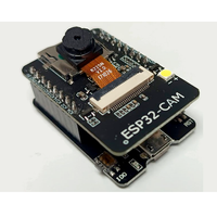
AI Thinker ESP32-CAM Development Board Pinout and Technical Specifications
Code name: ESP32_DEV
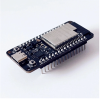
AI Thinker ESP32-CAM development board is based on esp32 microcontroller and uses xtensa architecture. This development board has a maximum CPU frequency of 240 MHz and a flash size of 4MB.
🔗 Quick Links
🛒 Price


📊 AI Thinker ESP32-CAM Specs
Below you can find the specifications of AI Thinker ESP32-CAM, such as features, connectivity options, and AI Thinker ESP32-CAM technical specs.
✨ Features
- 40 digital IO pins
- 16 external interrupt pins
- 16 analog input pins
- 19 PWM pins
🛰️ Connectivity
- WiFi: 802.11 b/g/n (2.4 GHz)
- Bluetooth: 4.2
- BLE: 4.2
📐 Technical specs
| Microcontroller | esp32 |
| Clock Speed | 240 MHz |
| Flash size | 4MB |
| Architecture | xtensa |
🔌 AI Thinker ESP32-CAM Pinout
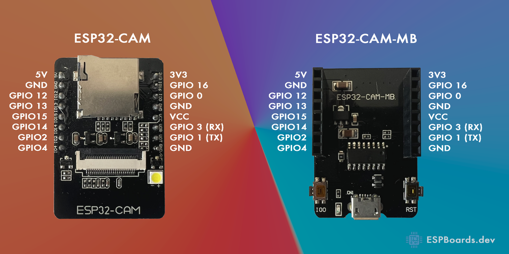
The ESP32-CAM pinout is designed to provide versatile functionality for camera-based IoT applications. It features essential power pins like 5V, 3.3V, and GND, ensuring stable power delivery for both the ESP32 chip and connected peripherals.
For communication, the ESP32-CAM includes RX and TX for UART, making it easy to connect to external serial devices. Additionally, SDA and SCL support I2C communication, while SPI pins like MISO, MOSI, SCK, and SS enable high-speed data transfer for sensors, displays, and storage.
One of the key features of the ESP32-CAM is its dedicated camera interface, which includes multiple GPIOs for connecting the OV2640 camera module. It also has a microSD card slot, allowing you to store captured images and videos easily.
Since the ESP32-CAM does not have a built-in USB-to-serial converter, programming requires an external FTDI or USB-to-TTL adapter connected to the RX and TX pins. Proper boot mode selection is also necessary when flashing firmware.
⚠️ Pins to Avoid or Use with Caution
| Pin Name | Label | Reason to Avoid |
|---|---|---|
| IO0 | BOOT | Must be pulled low to enter flash mode. Avoid using as a regular GPIO. |
| IO4 | CAM_D2 | Used by the camera module. Avoid using if the camera is in use. |
| IO12 | MTDI | Bootstrapping pin. Can cause issues if pulled high at startup. |
| IO13 | MTCK | Used for flash mode configuration. Avoid using if unsure. |
| IO14 | MTMS | Connected to the camera. Avoid using as a general GPIO. |
| IO15 | MTDO | Strapping pin. Can interfere with boot mode if pulled incorrectly. |
For general GPIO usage, IO2, IO16, and IO17 are the safest and most flexible choices. 🚀
🗺️ AI Thinker ESP32-CAM Pins Mapping Arduino IDE
Below you can find the AI Thinker ESP32-CAM pinout. This development board provides 40 digital IO pins, out of which 16 can be used as an external interrupt pins , 16 as analog input pins and 19 pins have Pulse-Width Modulation (PWM) .
| Pin | Analog | Touch | PWM | Other |
|---|---|---|---|---|
| 0 | A11 | T1 | ||
| 1 | PWM | TX | ||
| 2 | A12 | T2 | PWM | |
| 3 | PWM | RX | ||
| 4 | A10 | T0 | PWM | |
| 5 | PWM | SS | ||
| 12 | A15 | T5 | PWM | |
| 13 | A14 | T4 | PWM | |
| 14 | A16 | T6 | PWM | |
| 15 | A13 | T3 | PWM | |
| 18 | PWM | SCK | ||
| 19 | PWM | MISO | ||
| 21 | PWM | SDA | ||
| 22 | PWM | SCL | ||
| 23 | PWM | MOSI | ||
| 25 | A18 | PWM | DAC1 | |
| 26 | A19 | PWM | DAC2 | |
| 27 | A17 | T7 | PWM | |
| 32 | A4 | T9 | PWM | |
| 33 | A5 | T8 | PWM | |
| 34 | A6 | |||
| 35 | A7 | |||
| 36 | A0 | |||
| 39 | A3 |
🛠️ Default Tools
| Bootloader tool | esptool_py |
| Uploader tool | esptool_py |
| Network uploader tool | esp_ota |
| Bootloader address | 0x1000 |
| Flash mode | |
| Boot mode | |
| PSRAM type | |
| Maximum upload size | 3072 Kb (3145728 B) |
| Maximum data size | 320 Kb (327680 B) |
The AI Thinker ESP32-CAM development board by default uses esptool_py uploader tool, esp_ota network uploader tool for Over-the-air (OTA) uploads and esptool_py bootloader tool. The bootloader starts at address "0x1000". Flash mode and boot mode for AI Thinker ESP32-CAM development board by default is and respectively.