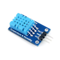
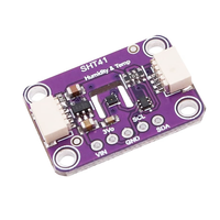
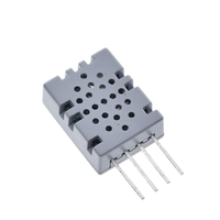
ESP32 BME280 Temperature and Humidity Sensor
The BME280 is a compact digital sensor by Bosch Sensortec, designed for measuring temperature, humidity, and pressure with high accuracy and low power consumption. It supports both I²C and SPI communication protocols, making it versatile for integration into IoT devices, weather stations, and portable electronics. Operating within a wide range of environmental conditions, it features a small 2.5mm x 2.5mm package.
🔗 Quick Links
🛒 BME280 Price
ℹ️ About BME280 Temperature and Humidity Sensor
The BME280, developed by Bosch Sensortec, is a highly integrated environmental sensor that provides accurate temperature, humidity, and pressure measurements. Its low power consumption and compact size make it perfect for IoT, wearables, and weather monitoring applications.
⚡ Key Features #
- 3-in-1 Sensing – Measures temperature (-40°C to 85°C), humidity (0–100% RH), and pressure (300–1100 hPa).
- Multiple Communication Interfaces – Supports I²C and SPI for flexible integration.
- Ultra-Low Power – Consumes as little as 1.8 µA, ideal for battery-powered devices.
- Compact Design – Small 2.5 × 2.5 × 0.93 mm form factor for space-constrained applications.
🔗 Learn more about the BME280 sensor.
⚙️ BME280 Sensor Technical Specifications
Below you can see the BME280 Temperature and Humidity Sensor Technical Specifications. The sensor is compatible with the ESP32, operating within a voltage range suitable for microcontrollers. For precise details about its features, specifications, and usage, refer to the sensor’s datasheet.
- Type: environment
- Protocol: I2C, SPI
- Interface: I2C (up to 3.4 MHz), SPI (3- and 4-wire, up to 10 MHz)
- Accuracy: ±3% RH (humidity), ±0.5 °C (temperature), ±1 hPa (pressure)
- Operating Range: -40°C to 85°C, 0 – 100% RH, 300 – 1100 hPa
- Supply Voltage: 1.71V to 3.6V for VDD, 1.2V to 3.6V for VDDIO
- Current Consumption: 1.8 µA @ 1 Hz (humidity + temp), 3.6 µA @ 1 Hz (humidity + pressure + temp)
- Sleep Mode Current: 0.1 µA
- Response Time: 1 second (humidity, τ63%)
- Package Dimensions: 2.5 mm x 2.5 mm x 0.93 mm (LGA)
🔌 BME280 Sensor Pinout
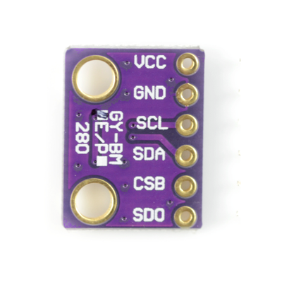
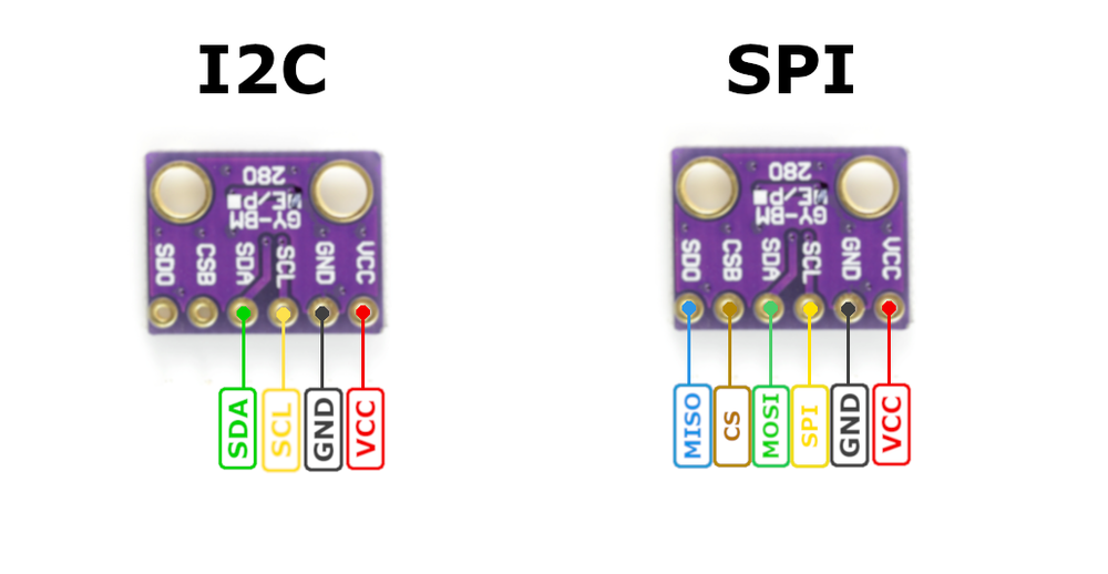
Below you can see the pinout for the BME280 Temperature and Humidity Sensor. The VCC pin is used to supply power to the sensor, and it typically requires 3.3V or 5V (refer to the datasheet for specific voltage requirements). The GND pin is the ground connection and must be connected to the ground of your ESP32!
When using the I2C protocol, the sensor communicates via the SCL (clock) and SDA (data) pins. These pins connect to the respective clock and data lines of the microcontroller. The I2C protocol is efficient for minimal wiring, requiring only two data pins. For the SPI protocol, the sensor uses four pins: SCK (clock), SDI (MOSI), SDO (MISO), and CS (chip select). This setup provides higher data transfer speeds and is suitable for applications requiring fast and reliable communication. Both protocols also use VIN (or VCC) for power (typically 3.3V or 5V) and GND for grounding.
🧵 BME280 Wiring with ESP32
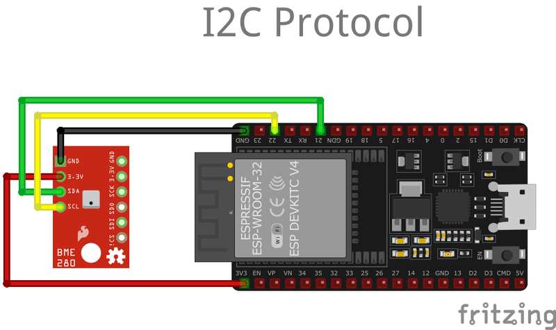
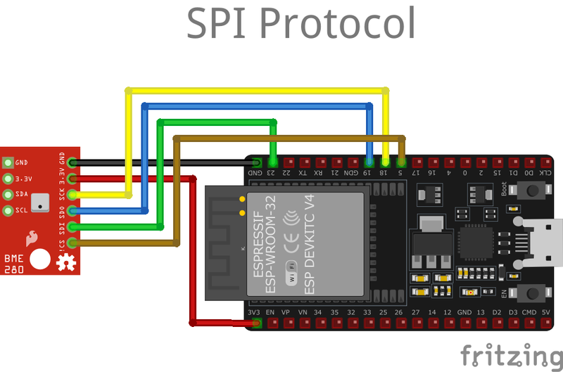
Below you can see the wiring for the BME280 Temperature and Humidity Sensor with the ESP32. Connect the VCC pin of the sensor to the 3.3V pin on the ESP32 or external power supply for power and the GND pin of the sensor to the GND pin of the ESP32. Depending on the communication protocol of the sensor (e.g., I2C, SPI, UART, or analog), connect the appropriate data and clock or signal pins to compatible GPIO pins on the ESP32, as shown below in the wiring diagram.
The GPIO pins for I2C communication with BME280 and ESP32 is as following:
- SCK (SCL Pin): GPIO 22
- SDI (SDA Pin): GPIO 21
The GPIO pins for SPI (Serial Peripheral Interface) communication with BME280 and ESP32 is as following:
- SCK (SPI Clock): GPIO 18
- SDO (MISO): GPIO 19
- SDI (MOSI): GPIO 23
- CS (Chip Select): GPIO 5
🛠️ BME280 Temperature and Humidity Sensor Troubleshooting
This guide outlines a systematic approach to troubleshoot and resolve common problems with the . Start by confirming that the hardware connections are correct, as wiring mistakes are the most frequent cause of issues. If you are sure the connections are correct, follow the below steps to debug common issues.
🔍 I2C Sensor Found, but Could not find a valid BME280 sensor
Issue: The I2C scanner detects the BME280 sensor, but example sketches fail to initialize it.
I2C device found at addres 0x76Could not find a valid BME280 sensor, check wiring, address, sensor ID!
Some cheeap BME280 named sensors does not actually work with the Adafruit library, due to the I2C Bus Timing - different libraries configure I2C clock speeds differently, which might cause issues with sensors that cannot keep up with faster communication.
Solution: Try using different library instead of Adafruit_BME280.h, such as the BME280.h
🆔 Incorrect Sensor Identification
Issue: The sensor is identified incorrectly, leading to initialization failures..
SensorID was: 0x0ID of 0xFF probably means a bad address, a BMP 180 or BMP 085ID of 0x56-0x58 represents a BMP 280,ID of 0x60 represents a BME 280.ID of 0x61 represents a BME 680.
Some modules labeled as BME280 are actually BMP280, which lacks the humidity sensor.
Solution: If the sensor is a BMP280, use the BMP280 library (Adafruit_BMP280.h) instead of the BME280 library.
💻 Code Examples
Below you can find code examples of BME280 Temperature and Humidity Sensor with ESP32 in several frameworks:
If you encounter issues while using the BME280 Temperature and Humidity Sensor, check the Common Issues Troubleshooting Guide.

ESP32 BME280 Arduino IDE Code Example
Fill in your main Arduino IDE sketch file with the following code to use the BME280 Temperature and Humidity Sensor:
#include <Wire.h>
#include <Adafruit_Sensor.h>
#include <Adafruit_BME280.h>

/* Uncomment these lines if using SPI interface
#include <SPI.h>
#define SPI_CLK 18
#define SPI_MISO 19
#define SPI_MOSI 23
#define SPI_CS 5
*/

#define SEA_LEVEL_PRESSURE (1013.25) // Standard sea level pressure

Adafruit_BME280 environmentSensor; // Using I2C for communication
//Adafruit_BME280 environmentSensor(SPI_CS); // Use for hardware SPI
//Adafruit_BME280 environmentSensor(SPI_CS, SPI_MOSI, SPI_MISO, SPI_CLK); // Use for software SPI

unsigned long refreshInterval;

void setup() {
  Serial.begin(9600);
  Serial.println(F("Initializing BME280 Sensor"));

  bool initSuccess;

  // Initialize sensor with default settings (I2C address 0x76)
  initSuccess = environmentSensor.begin(0x76);
  if (!initSuccess) {
    Serial.println("Sensor initialization failed. Verify wiring and connections.");
    while (1); // Halt execution if sensor is not found
  }

  Serial.println("-- Running Default Configuration --");
  refreshInterval = 1000; // Data refresh every 1000 ms

  Serial.println();
}

void loop() {
  displaySensorData();
  delay(refreshInterval);
}

void displaySensorData() {
  Serial.print("Temperature: ");
  Serial.print(environmentSensor.readTemperature());
  Serial.println(" °C");

  // Optional: Uncomment for Fahrenheit conversion
  /*Serial.print("Temperature: ");
  Serial.print(1.8 * environmentSensor.readTemperature() + 32);
  Serial.println(" °F");*/

  Serial.print("Pressure: ");
  Serial.print(environmentSensor.readPressure() / 100.0F);
  Serial.println(" hPa");

  Serial.print("Estimated Altitude: ");
  Serial.print(environmentSensor.readAltitude(SEA_LEVEL_PRESSURE));
  Serial.println(" meters");

  Serial.print("Humidity: ");
  Serial.print(environmentSensor.readHumidity());
  Serial.println(" %");

  Serial.println();
}
This code is configured for I2C communication by default, with the BME280 sensor initialized using its default I2C address (0x76). However, it includes commented-out sections for using SPI communication as an alternative protocol.
Library Installation #
To use this code, you need to install the Adafruit BME280 library. Follow these steps:
- Open Arduino IDE.
- Navigate to Sketch → Include Library → Manage Libraries.
- Search for "Adafruit BME280" and install it.
Alternatively, you can download the library from the official Adafruit GitHub repository:
🔗 Adafruit BME280 Library
Connect your ESP32 to your computer via a USB cable, Ensure the correct Board and Port are selected under Tools, Click the "Upload" button in the Arduino IDE to compile and upload the code to your ESP32.
ESP32 BME280 ESP-IDF Code ExampleExample in Espressif IoT Framework (ESP-IDF)
If you're using ESP-IDF to work with the BME280 Temperature and Humidity Sensor, here's how you can set it up and read data from the sensor. Fill in this code in the main ESP-IDF file:
#include <stdio.h>
#include "esp_log.h"
#include "bme280.h" // BME280 driver for ESP-IDF (you need to include this library)

#define I2C_MASTER_SCL_IO 22     // GPIO number for I2C SCL
#define I2C_MASTER_SDA_IO 21     // GPIO number for I2C SDA
#define I2C_MASTER_NUM I2C_NUM_0 // I2C port number
#define I2C_MASTER_FREQ_HZ 100000 // I2C frequency
#define BME280_I2C_ADDR 0x76      // BME280 I2C address

void app_main(void)
{
   static i2c_bus_handle_t i2c_bus = NULL;
    static bme280_handle_t bme280 = NULL;

    //Step1: Init I2C bus
    i2c_config_t conf1 = {
        .mode = I2C_MODE_MASTER,
        .sda_io_num = I2C_MASTER_SDA_IO,
        .sda_pullup_en = GPIO_PULLUP_ENABLE,
        .scl_io_num = I2C_MASTER_SCL_IO,
        .scl_pullup_en = GPIO_PULLUP_ENABLE,
        .master.clk_speed = I2C_MASTER_FREQ_HZ,
    };
    i2c_bus = i2c_bus_create(I2C_MASTER_NUM, &conf1);

    //Step2: Init bme280
    bme280 = bme280_create(i2c_bus, BME280_I2C_ADDRESS_DEFAULT);
    bme280_default_init(bme280);

    //Step3: Read temperature, humidity and pressure
    float temperature = 0.0, humidity = 0.0, pressure = 0.0;
    bme280_read_temperature(bme280, &temperature);
    bme280_read_humidity(bme280, &humidity);
    bme280_read_pressure(bme280, &pressure);
}
Key Features #
- I2C communication is configured with SDA on GPIO 21 and SCL on GPIO 22 at 100 kHz.
- The BME280 sensor is initialized at I2C address
0x76. - The sensor readings include temperature, humidity, and pressure.
Library Requirement #
This code uses the BME280 driver for ESP-IDF, which must be installed. To install the required library, run the following command in the ESP-IDF environment:
idf.py add-dependency "espressif/bme280^0.1.1"Alternatively, you can download the library from the official ESP-IDF component registry:
🔗 ESP-IDF BME280 Library
Code Breakdown #
I2C Initialization
- The I2C bus is configured using
i2c_config_tand initialized withi2c_bus_create(). - The SDA and SCL lines have pull-up resistors enabled.
- The I2C bus is configured using
BME280 Sensor Setup
- The sensor is initialized with
bme280_create(), using the I2C bus handle. - The function
bme280_default_init()configures the sensor with default settings.
- The sensor is initialized with
Reading Sensor Data
- The code retrieves temperature, humidity, and pressure data using:
bme280_read_temperature()bme280_read_humidity()bme280_read_pressure()
- These values can be printed to the console or used in further processing.
- The code retrieves temperature, humidity, and pressure data using:
Customization #
- This implementation can be expanded to log data, send values to a cloud server, or trigger events based on environmental conditions.
- Additional configurations can be made to adjust sampling rates, filtering, or power modes.
This setup ensures reliable communication with the BME280 sensor using ESP-IDF’s I2C API.
Update the I2C pins (I2C_MASTER_SDA_IO and I2C_MASTER_SCL_IO) to match your ESP32 hardware setup, Use idf.py build to compile the project, Use idf.py flash to upload the code to your ESP32.
ESP32 BME280 ESPHome Code Example
Fill in this configuration in your ESPHome YAML configuration file (example.yml) to integrate the BME280 Temperature and Humidity Sensor
sensor:
  - platform: bme280_i2c
    temperature:
      name: "BME280 Temperature"
    pressure:
      name: "BME280 Pressure"
    humidity:
      name: "BME280 Humidity"


# Example configuration entry SPI
sensor:
  - platform: bme280_spi
    temperature:
      name: "BME280 Temperature"
    pressure:
      name: "BME280 Pressure"
    humidity:
      name: "BME280 Humidity"
    cs_pin: GPIOXX
The following YAML configuration sets up two sensor platforms for a BME280 sensor:
bme280_i2c:Configures the BME280 sensor using the I2C interface.The temperature, pressure, and humidity readings are named accordingly.bme280_spi:Configures the BME280 sensor using the SPI interface.It includes an additional parametercs_pinto specify the chip select pin.
Upload this code to your ESP32 using the ESPHome dashboard or the esphome run command.

ESP32 BME280 PlatformIO Code Example
For PlatformIO, make sure to configure the platformio.ini file with the appropriate environment and libraries, and then proceed with the code.
Configure platformio.ini
First, your platformio.ini should look like below. You might need to include some libraries as shown. Make sure to change the board to your ESP32:
[env:esp32dev]
platform = espressif32
board = esp32dev
framework = arduino
monitor_speed = 115200

lib_deps =
    adafruit/Adafruit BME280 Library @ ^2.2.2
    adafruit/Adafruit Unified Sensor @ ^1.1.7

build_flags =
    -DBME280_I2C    ; Define if using I2C
    ; -DBME280_SPI ; Uncomment if using SPI
ESP32 BME280 PlatformIO Example Code
Write this code in your PlatformIO project under the src/main.cpp file to use the BME280 Temperature and Humidity Sensor:
#include <Wire.h>
#include <Adafruit_Sensor.h>
#include <Adafruit_BME280.h>

// Define I2C address or SPI pins
#define SEALEVELPRESSURE_HPA (1013.25)
Adafruit_BME280 bme;

void setup() {
    Serial.begin(115200);
    if (!bme.begin(0x76)) { // Replace 0x76 with your I2C address
        Serial.println("Could not find a valid BME280 sensor, check wiring!");
        while (1);
    }
}

void loop() {
    Serial.print("Temperature = ");
    Serial.print(bme.readTemperature());
    Serial.println(" °C");

    Serial.print("Pressure = ");
    Serial.print(bme.readPressure() / 100.0F);
    Serial.println(" hPa");

    Serial.print("Humidity = ");
    Serial.print(bme.readHumidity());
    Serial.println(" %");

    Serial.println();
    delay(2000);
}
This program configures a BME280 sensor using PlatformIO. Key steps include:
- Library Inclusions: Include
Wire.h,Adafruit_Sensor.h, andAdafruit_BME280.hfor I2C communication and sensor interfacing. - PlatformIO Setup: Add required libraries in
platformio.iniunderlib_deps:lib_deps = adafruit/Adafruit BME280 Library @ ^2.2.2 adafruit/Adafruit Unified Sensor @ ^1.1.7 - Sensor Initialization: Use
bme.begin(0x76)for I2C (replace with0x77if needed). - Data Reading: Read temperature, pressure, and humidity with
bme.readTemperature(),bme.readPressure(), andbme.readHumidity().
Upload the code to your ESP32 using the PlatformIO "Upload" button in your IDE or the pio run --target upload command.
ESP32 BME280 MicroPython Code Example
Fill in this script in your MicroPython main.py file (main.py) to integrate the BME280 Temperature and Humidity Sensor with your ESP32.
import time
from machine import I2C, Pin
from bme280 import BME280

# Initialize I2C
i2c = I2C(1, scl=Pin(22), sda=Pin(21))  # Adjust pins as needed (e.g., SCL=22, SDA=21)

# Initialize BME280
bme = BME280(i2c=i2c)

while True:
    # Read data from the BME280
    temperature = bme.temperature
    pressure = bme.pressure
    humidity = bme.humidity

    # Print data to the console
    print("Temperature:", temperature)
    print("Pressure:", pressure)
    print("Humidity:", humidity)
    print("-" * 30)

    time.sleep(2)  # Wait 2 seconds before the next reading
This MicroPython code reads data from a BME280 sensor using I2C. Key steps:
from machine import I2C, Pin: Initializes I2C communication with the specified pins (e.g., SCL=22, SDA=21).
from bme280 import BME280: Imports the BME280 library, which must be in the same directory.
bme = BME280(i2c=i2c): Creates a BME280 object to interact with the sensor.
The main loop reads temperature, pressure, and humidity using bme.temperature, bme.pressure, and bme.humidity, printing the results every 2 seconds.
Upload this code to your ESP32 using a MicroPython-compatible IDE, such as Thonny, uPyCraft, or tools like ampy.
Conclusion
We went through technical specifications of BME280 Temperature and Humidity Sensor, its pinout, connection with ESP32 and BME280 Temperature and Humidity Sensor code examples with Arduino IDE, ESP-IDF, ESPHome and PlatformIO.

