ESP32 DS1307 Real-Time Clock (RTC)
The DS1307 is a widely used real-time clock module with I2C communication. It supports leap year compensation, battery-backed operation, and 56 bytes of user-accessible SRAM, making it ideal for embedded systems and low-power applications.
⬇️ Jump to Code Examples
🔗 Quick Links
🛒 DS1307 Price
ℹ️ About DS1307 Real-Time Clock (RTC)
The DS1307 is a widely used real-time clock (RTC) module designed to maintain accurate timekeeping, including automatic leap year compensation. Unlike the DS1302, it communicates via I²C, simplifying integration with ESP32, Arduino, and other microcontrollers.
⚡ Key Features #
- Real-Time Clock Functionality – Tracks seconds, minutes, hours, day, date, month, and year.
- I²C Communication – Easier integration than 3-wire serial RTCs like the DS1302.
- 56-Byte Battery-Backed SRAM – Stores small user data for embedded applications.
- Battery Backup Support – Maintains timekeeping during power loss (no trickle charger like DS1302).
With its I²C interface and reliable backup capabilities, the DS1307 is an excellent choice for data loggers, automation systems, and real-time event tracking. 🚀
🔗 Looking for a different RTC? Check out the DS1302 for a 3-wire alternative with trickle charging.
⚙️ DS1307 Sensor Technical Specifications
Below you can see the DS1307 Real-Time Clock (RTC) Technical Specifications. The sensor is compatible with the ESP32, operating within a voltage range suitable for microcontrollers. For precise details about its features, specifications, and usage, refer to the sensor’s datasheet.
- Protocol: I2C
- Timekeeping Range: Seconds to Year (up to 2100)
- Power Supply Voltage: 4.5V to 5.5V (VCC), 2.0V to 3.5V (VBAT)
- Backup Battery Current: <500 nA at 3.0V
- Interface: I2C (400 kHz)
- Data Storage: 56 bytes of battery-backed SRAM
- Clock Accuracy: Determined by external crystal
- Operating Temperature: 0°C to +70°C (Commercial), -40°C to +85°C (Industrial)
🔌 DS1307 Sensor Pinout
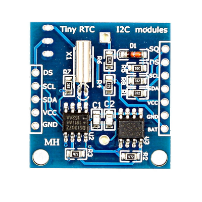
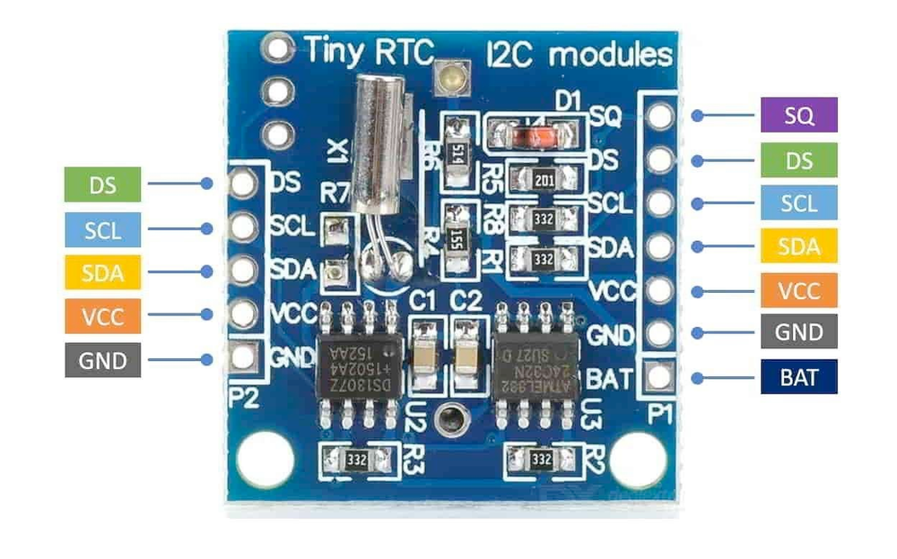
Below you can see the pinout for the DS1307 Real-Time Clock (RTC). The VCC pin is used to supply power to the sensor, and it typically requires 3.3V or 5V (refer to the datasheet for specific voltage requirements). The GND pin is the ground connection and must be connected to the ground of your ESP32!
The DS1307 pinout is as follows:
- VCC: Primary power supply input (5V).
- GND: Ground connection.
- SDA: Serial Data for I2C communication.
- SCL: Serial Clock for I2C communication.
- X1: Connection for 32.768 kHz crystal oscillator.
- X2: Connection for 32.768 kHz crystal oscillator.
- VBAT: Battery backup power input (3V).
🧵 DS1307 Wiring with ESP32
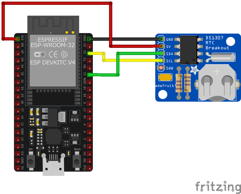
Below you can see the wiring for the DS1307 Real-Time Clock (RTC) with the ESP32. Connect the VCC pin of the sensor to the 3.3V pin on the ESP32 or external power supply for power and the GND pin of the sensor to the GND pin of the ESP32. Depending on the communication protocol of the sensor (e.g., I2C, SPI, UART, or analog), connect the appropriate data and clock or signal pins to compatible GPIO pins on the ESP32, as shown below in the wiring diagram.
VCC to a 5V power supply, GND to ground, SDA to the microcontroller's I2C data pin, and SCL to the I2C clock pin. Connect a 32.768 kHz crystal to X1 and X2, and attach a 3V coin cell battery to VBAT to maintain timekeeping during power loss.🛠️ DS1307 Real-Time Clock (RTC) Troubleshooting
This guide outlines a systematic approach to troubleshoot and resolve common problems with the . Start by confirming that the hardware connections are correct, as wiring mistakes are the most frequent cause of issues. If you are sure the connections are correct, follow the below steps to debug common issues.
⚠️ Incorrect Time or Date Displayed
Issue: The DS1307 RTC module displays incorrect time or date information.
Possible causes include improper initialization, incorrect data retrieval methods, or communication errors.
Solution: Ensure that the RTC is properly initialized in your code, disabling write protection and setting the clock to run mode. Use reliable libraries and functions to set and retrieve time data. Verify that the communication between the microcontroller and the RTC is functioning correctly, and consider implementing error-checking mechanisms to detect and handle communication issues.
⏰ RTC Not Advancing Time Correctly
Issue: The DS1307 RTC module displays a constant time or advances time incorrectly.
Possible causes include insufficient power supply, incorrect wiring, or a defective module.
Solution: Ensure that the module is connected to a stable power source, with VCC connected to 5V and GND to ground. Verify that the SDA and SCL pins are correctly connected to the appropriate digital pins on the microcontroller. If the problem persists, consider replacing the DS1307 module, as some units, especially from unreliable sources, may be faulty.
🔌 Communication Issues with Microcontroller
Issue: The microcontroller fails to communicate with the DS1307 RTC module.
Possible causes include incorrect I2C address configuration, improper wiring, or lack of pull-up resistors on the I2C lines.
Solution: Verify that the sensor's I2C address matches the address specified in your code; the default address is 0x68. Ensure that the SDA and SCL lines are correctly connected to the corresponding pins on the microcontroller. Check for the presence of appropriate pull-up resistors (typically 4.7kΩ) on the I2C lines if they are not already included on the sensor module.
🔄 Time Resets After Power Loss
Issue: The DS1307 RTC loses track of time after a power cycle.
Possible causes include a missing or depleted backup battery, or incorrect wiring of the backup power supply.
Solution: Install a backup battery (e.g., a CR2032 coin cell) to the VBAT pin to maintain timekeeping during power loss. Ensure that the battery is fresh and properly connected. Verify that the VCC pin is connected to the main power supply, and that the module is configured to switch to the backup battery when the main power is unavailable.
💻 Code Examples
Below you can find code examples of DS1307 Real-Time Clock (RTC) with ESP32 in several frameworks:
If you encounter issues while using the DS1307 Real-Time Clock (RTC), check the Common Issues Troubleshooting Guide.
ESP32 DS1307 Arduino IDE Code Example
Fill in your main Arduino IDE sketch file with the following code to use the DS1307 Real-Time Clock (RTC):
#include <Wire.h>
#include <RTClib.h>

RTC_DS1307 rtc;

void setup() {
    Serial.begin(9600);
    Wire.begin();
    if (!rtc.begin()) {
        Serial.println("Couldn't find RTC");
        while (1);
    }
    if (!rtc.isrunning()) {
        rtc.adjust(DateTime(2023, 12, 4, 14, 30, 0)); // Set initial date/time: YYYY, MM, DD, HH, MM, SS
    }
}

void loop() {
    DateTime now = rtc.now();
    Serial.print("Time: ");
    Serial.print(now.hour());
    Serial.print(":");
    Serial.print(now.minute());
    Serial.print(":");
    Serial.println(now.second());
    Serial.print("Date: ");
    Serial.print(now.year());
    Serial.print("/");
    Serial.print(now.month());
    Serial.print("/");
    Serial.println(now.day());
    delay(1000);
}
This Arduino sketch demonstrates how to use the DS1307 RTC module for timekeeping. The RTClib library simplifies I2C communication and RTC management. The rtc.adjust() function initializes the DS1307 with a specific date and time if it is not already running. In the loop(), the current date and time are fetched using the rtc.now() method and displayed on the Serial Monitor.
Connect your ESP32 to your computer via a USB cable, Ensure the correct Board and Port are selected under Tools, Click the "Upload" button in the Arduino IDE to compile and upload the code to your ESP32.
ESP32 DS1307 ESP-IDF Code ExampleExample in Espressif IoT Framework (ESP-IDF)
If you're using ESP-IDF to work with the DS1307 Real-Time Clock (RTC), here's how you can set it up and read data from the sensor. Fill in this code in the main ESP-IDF file:
#include <stdio.h>
#include "driver/i2c.h"
#include "ds1307.h"

#define I2C_MASTER_SCL_IO 22
#define I2C_MASTER_SDA_IO 21

void app_main(void) {
    i2c_config_t config = {
        .mode = I2C_MODE_MASTER,
        .sda_io_num = I2C_MASTER_SDA_IO,
        .scl_io_num = I2C_MASTER_SCL_IO,
        .sda_pullup_en = GPIO_PULLUP_ENABLE,
        .scl_pullup_en = GPIO_PULLUP_ENABLE,
        .master.clk_speed = 100000
    };
    i2c_param_config(I2C_NUM_0, &config);
    i2c_driver_install(I2C_NUM_0, I2C_MODE_MASTER, 0, 0, 0);

    ds1307_init(I2C_NUM_0);
    ds1307_set_datetime(2023, 12, 4, 14, 30, 0);

    while (1) {
        ds1307_datetime_t now;
        ds1307_get_datetime(&now);
        printf("Time: %02d:%02d:%02d\n", now.hour, now.minute, now.second);
        printf("Date: %04d/%02d/%02d\n", now.year, now.month, now.day);
        vTaskDelay(pdMS_TO_TICKS(1000));
    }
}
This ESP-IDF example demonstrates how to configure I2C for communication with the DS1307 RTC. The I2C pins (SDA: GPIO21, SCL: GPIO22) are configured, and the RTC is initialized. The ds1307_set_datetime() function sets the initial date and time, while the ds1307_get_datetime() function retrieves the current time and date in a loop, displaying them on the console.
Update the I2C pins (I2C_MASTER_SDA_IO and I2C_MASTER_SCL_IO) to match your ESP32 hardware setup, Use idf.py build to compile the project, Use idf.py flash to upload the code to your ESP32.
ESP32 DS1307 ESPHome Code Example
Fill in this configuration in your ESPHome YAML configuration file (example.yml) to integrate the DS1307 Real-Time Clock (RTC)
i2c:
  sda: GPIO21
  scl: GPIO22

sensor:
  - platform: ds1307
    id: ds1307_time
    update_interval: 1s

text_sensor:
  - platform: custom
    lambda: |-
      auto my_sensor = new DS1307Sensor(id(ds1307_time));
      return {my_sensor};
    sensors:
      - name: "DS1307 Date and Time"
The ESPHome configuration for the DS1307 RTC sets up the I2C interface with SDA on GPIO21 and SCL on GPIO22. The sensor platform is used to periodically fetch the date and time, which are displayed with an update interval of 1 second.
Upload this code to your ESP32 using the ESPHome dashboard or the esphome run command.

ESP32 DS1307 PlatformIO Code Example
For PlatformIO, make sure to configure the platformio.ini file with the appropriate environment and libraries, and then proceed with the code.
Configure platformio.ini
First, your platformio.ini should look like below. You might need to include some libraries as shown. Make sure to change the board to your ESP32:
[env:esp32dev]
platform = espressif32
board = esp32dev
framework = arduino
monitor_speed = 115200
ESP32 DS1307 PlatformIO Example Code
Write this code in your PlatformIO project under the src/main.cpp file to use the DS1307 Real-Time Clock (RTC):
#include <Wire.h>
#include <RTClib.h>

RTC_DS1307 rtc;

void setup() {
    Serial.begin(115200);
    Wire.begin(21, 22); // SDA: GPIO21, SCL: GPIO22
    if (!rtc.begin()) {
        Serial.println("Couldn't find RTC");
        while (1);
    }
    if (!rtc.isrunning()) {
        rtc.adjust(DateTime(2023, 12, 4, 14, 30, 0)); // Set initial date/time
    }
}

void loop() {
    DateTime now = rtc.now();
    Serial.print("Time: ");
    Serial.print(now.hour());
    Serial.print(":");
    Serial.print(now.minute());
    Serial.print(":");
    Serial.println(now.second());
    Serial.print("Date: ");
    Serial.print(now.year());
    Serial.print("/");
    Serial.print(now.month());
    Serial.print("/");
    Serial.println(now.day());
    delay(1000);
}
This PlatformIO code demonstrates how to use the DS1307 RTC with I2C communication (SDA: GPIO21, SCL: GPIO22). The code initializes the RTC, sets the initial date and time if required, and fetches the current time and date in a loop, displaying them every second.
Upload the code to your ESP32 using the PlatformIO "Upload" button in your IDE or the pio run --target upload command.
ESP32 DS1307 MicroPython Code Example
Fill in this script in your MicroPython main.py file (main.py) to integrate the DS1307 Real-Time Clock (RTC) with your ESP32.
from machine import I2C, Pin
import time

# DS1307 I2C address
DS1307_ADDRESS = 0x68

def bcd_to_decimal(bcd):
    return (bcd >> 4) * 10 + (bcd & 0x0F)

def decimal_to_bcd(decimal):
    return ((decimal // 10) << 4) | (decimal % 10)

def set_time(i2c, year, month, day, hour, minute, second):
    data = [decimal_to_bcd(second), decimal_to_bcd(minute), decimal_to_bcd(hour),
            decimal_to_bcd(day), decimal_to_bcd(month), decimal_to_bcd(year - 2000)]
    i2c.writeto_mem(DS1307_ADDRESS, 0x00, bytes(data))
    # Start the clock by ensuring the CH (clock halt) bit is cleared
    control = i2c.readfrom_mem(DS1307_ADDRESS, 0x00, 1)[0] & 0x7F
    i2c.writeto_mem(DS1307_ADDRESS, 0x00, bytes([control]))

def get_time(i2c):
    data = i2c.readfrom_mem(DS1307_ADDRESS, 0x00, 7)
    second = bcd_to_decimal(data[0] & 0x7F)
    minute = bcd_to_decimal(data[1])
    hour = bcd_to_decimal(data[2] & 0x3F)
    day = bcd_to_decimal(data[4])
    month = bcd_to_decimal(data[5])
    year = bcd_to_decimal(data[6]) + 2000
    return year, month, day, hour, minute, second

# Initialize I2C
i2c = I2C(0, scl=Pin(22), sda=Pin(21))

# Set initial time
set_time(i2c, 2023, 12, 4, 14, 30, 0)

# Loop to read time
while True:
    year, month, day, hour, minute, second = get_time(i2c)
    print(f"Time: {hour:02}:{minute:02}:{second:02}, Date: {year:04}/{month:02}/{day:02}")
    time.sleep(1)
This MicroPython script interfaces with the DS1307 RTC over I²C using SDA (GPIO21) and SCL (GPIO22). The set_time() function initializes the DS1307 with the provided date and time, ensuring the clock is running by clearing the CH (clock halt) bit. The get_time() function reads the current time and date from the DS1307, decodes the BCD values into integers, and returns them. The main loop continuously retrieves the current date and time and prints them every second.
Upload this code to your ESP32 using a MicroPython-compatible IDE, such as Thonny, uPyCraft, or tools like ampy.
Conclusion
We went through technical specifications of DS1307 Real-Time Clock (RTC), its pinout, connection with ESP32 and DS1307 Real-Time Clock (RTC) code examples with Arduino IDE, ESP-IDF, ESPHome and PlatformIO.

