ESP32 Sharp GP2Y1010AU0F Optical Dust Sensor
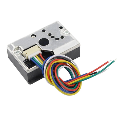
The Sharp GP2Y1010AU0F is an optical dust sensor designed for air quality monitoring. It detects fine particles like cigarette smoke by measuring the reflected light from an internal infrared LED. The sensor provides an analog voltage output proportional to the dust concentration, making it suitable for integration into air purifiers and HVAC systems.
Jump to Code Examples
Quick Links
GP2Y1010AU0F Price
About Sharp GP2Y1010AU0F Optical Dust Sensor
The Sharp GP2Y1010AU0F is an optical air quality sensor designed to detect dust particles in the air. It utilizes an infrared emitting diode (IR LED) and a phototransistor positioned diagonally to detect the reflected light from dust particles. This configuration allows the sensor to effectively detect very fine particles, such as cigarette smoke, making it suitable for air purifier systems. The GP2Y1010AU0F provides an analog voltage output proportional to the dust density, which can be read by an analog-to-digital converter (ADC) on a microcontroller.GP2Y1010AU0F Sensor Technical Specifications
Below you can see the Sharp GP2Y1010AU0F Optical Dust Sensor Technical Specifications. The sensor is compatible with the ESP32, operating within a voltage range suitable for microcontrollers. For precise details about its features, specifications, and usage, refer to the sensor’s datasheet.
- Protocol: Analog
- Operating Voltage: 4.5V to 5.5V
- Current Consumption: Max 20 mA
- Output Type: Analog voltage
- Detection Range: 0 to 0.5 mg/m³
- Dimensions: 46.0 x 30.0 x 17.6 mm
GP2Y1010AU0F Sensor Pinout
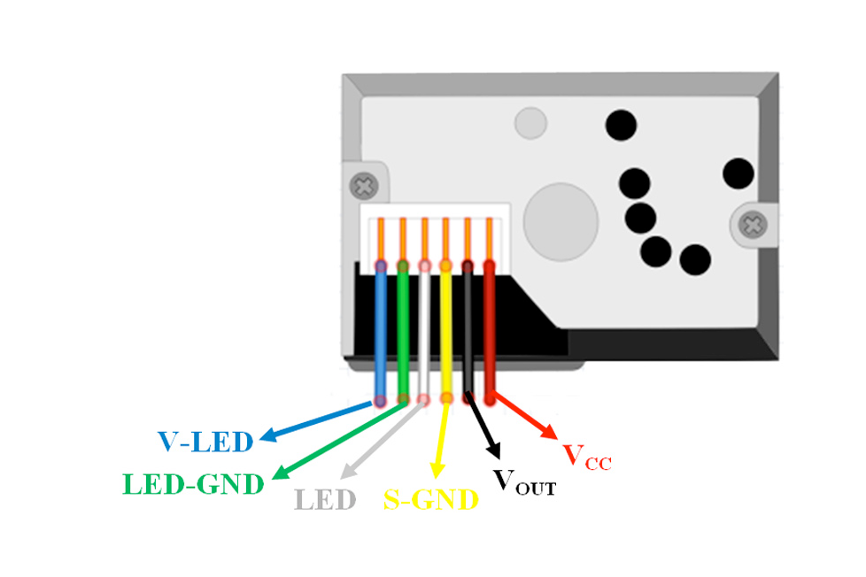
Below you can see the pinout for the Sharp GP2Y1010AU0F Optical Dust Sensor. The VCC pin is used to supply power to the sensor, and it typically requires 3.3V or 5V (refer to the datasheet for specific voltage requirements). The GND pin is the ground connection and must be connected to the ground of your ESP32!
The GP2Y1010AU0F pinout is as follows:
- Pin 1 (V-LED): LED power supply (typically connected to 5V through a 150Ω resistor).
- Pin 2 (LED-GND): LED ground.
- Pin 3 (LED): LED control input (connect to a digital output pin on the microcontroller).
- Pin 4 (S-GND): Signal ground.
- Pin 5 (Vo): Analog voltage output proportional to dust density (connect to an analog input pin on the microcontroller).
- Pin 6 (Vcc): Power supply (typically 5V).
GP2Y1010AU0F Wiring with ESP32
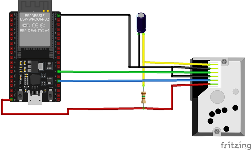
Below you can see the wiring for the Sharp GP2Y1010AU0F Optical Dust Sensor with the ESP32. Connect the VCC pin of the sensor to the 3.3V pin on the ESP32 or external power supply for power and the GND pin of the sensor to the GND pin of the ESP32. Depending on the communication protocol of the sensor (e.g., I2C, SPI, UART, or analog), connect the appropriate data and clock or signal pins to compatible GPIO pins on the ESP32, as shown below in the wiring diagram.
Vcc to the 5V power supply, LED-GND and S-GND to ground, Vo to an analog input pin (e.g., A0), and LED to a digital output pin (e.g., D9). Additionally, connect V-LED to 5V through a 150Ω resistor. This setup allows the microcontroller to control the sensor's LED and read the analog voltage output corresponding to dust density.Code Examples
Below you can find code examples of Sharp GP2Y1010AU0F Optical Dust Sensor with ESP32 in several frameworks:
If you encounter issues while using the Sharp GP2Y1010AU0F Optical Dust Sensor, check the Common Issues Troubleshooting Guide.

ESP32 GP2Y1010AU0F Arduino IDE Code Example
Fill in your main Arduino IDE sketch file with the following code to use the Sharp GP2Y1010AU0F Optical Dust Sensor:
#include <GP2Y1010AU0F.h>

int measurePin = A0; // Connect dust sensor analog measure pin to Arduino A0
int ledPin = 9;    // Connect dust sensor LED pin to Arduino D9

GP2Y1010AU0F dustSensor(ledPin, measurePin); // Construct dust sensor object

void setup() {
    Serial.begin(9600);
    dustSensor.begin();
}

void loop() {
    float dustDensity = dustSensor.read();
    Serial.print("Dust Density = ");
    Serial.print(dustDensity);
    Serial.println(" µg/m³");
    delay(1000);
}
This Arduino sketch interfaces with the GP2Y1010AU0F dust sensor. It initializes the sensor using the GP2Y1010AU0F library, specifying the LED control pin (D9) and the analog measurement pin (A0). In the setup() function, the sensor is initialized. The loop() function reads the dust density in micrograms per cubic meter (µg/m³) every second and prints the value to the Serial Monitor.
Connect your ESP32 to your computer via a USB cable, Ensure the correct Board and Port are selected under Tools, Click the "Upload" button in the Arduino IDE to compile and upload the code to your ESP32.

ESP32 GP2Y1010AU0F ESP-IDF Code ExampleExample in Espressif IoT Framework (ESP-IDF)
If you're using ESP-IDF to work with the Sharp GP2Y1010AU0F Optical Dust Sensor, here's how you can set it up and read data from the sensor. Fill in this code in the main ESP-IDF file:
#include <stdio.h>
#include "driver/adc.h"
#include "driver/gpio.h"
#include "esp_adc_cal.h"

#define LED_PIN GPIO_NUM_4
#define ADC_CHANNEL ADC1_CHANNEL_0 // GPIO36 for analog input
#define DEFAULT_VREF 1100 // Default reference voltage in mV

void app_main(void) {
    // Configure the LED pin as output
    gpio_pad_select_gpio(LED_PIN);
    gpio_set_direction(LED_PIN, GPIO_MODE_OUTPUT);

    // Configure ADC for analog reading
    adc1_config_width(ADC_WIDTH_BIT_12);
    adc1_config_channel_atten(ADC_CHANNEL, ADC_ATTEN_DB_0);

    // Characterize ADC
    esp_adc_cal_characteristics_t *adc_chars = calloc(1, sizeof(esp_adc_cal_characteristics_t));
    esp_adc_cal_characterize(ADC_UNIT_1, ADC_ATTEN_DB_0, ADC_WIDTH_BIT_12, DEFAULT_VREF, adc_chars);

    while (1) {
        // Pulse the LED for dust measurement
        gpio_set_level(LED_PIN, 1);
        vTaskDelay(pdMS_TO_TICKS(0.28)); // Pulse width of 280µs
        gpio_set_level(LED_PIN, 0);

        // Read ADC value
        uint32_t raw = adc1_get_raw(ADC_CHANNEL);
        uint32_t voltage = esp_adc_cal_raw_to_voltage(raw, adc_chars);

        // Convert voltage to dust density (example conversion, customize for calibration)
        float dust_density = (voltage - 400) / 50.0; // µg/m³

        // Print the dust density
        printf("Dust Density: %.2f µg/m³\n", dust_density);

        vTaskDelay(pdMS_TO_TICKS(1000)); // Delay 1 second before the next reading
    }
}
This ESP-IDF example interfaces with the GP2Y1010AU0F dust sensor. The LED pin (GPIO4) is configured as an output to control the LED pulse, while the ADC channel (GPIO36) is set up for analog readings. The ADC is characterized with a default reference voltage of 1100 mV. In the main loop, the code pulses the LED for 280 microseconds, reads the analog output, converts the raw ADC value to voltage, and calculates the dust density. The dust density in µg/m³ is printed to the console every second.
Update the I2C pins (I2C_MASTER_SDA_IO and I2C_MASTER_SCL_IO) to match your ESP32 hardware setup, Use idf.py build to compile the project, Use idf.py flash to upload the code to your ESP32.

ESP32 GP2Y1010AU0F ESPHome Code Example
Fill in this configuration in your ESPHome YAML configuration file (example.yml) to integrate the Sharp GP2Y1010AU0F Optical Dust Sensor
sensor:
  - platform: adc
    pin: GPIO36
    name: "Dust Density"
    update_interval: 1s
    filters:
      - calibrate_linear:
          - 0.0 -> 0.0
          - 2.5 -> 0.5  # Adjust these values based on sensor calibration
    unit_of_measurement: "µg/m³"

gpio:
  - platform: output
    pin: GPIO4
    id: led_control

interval:
  - interval: 1s
    then:
      - output.turn_on: led_control
      - delay: 0.28ms
      - output.turn_off: led_control
This ESPHome configuration integrates the GP2Y1010AU0F sensor using an ADC for reading analog voltage and a GPIO output for controlling the LED. The ADC platform reads the dust sensor's output on GPIO36, and a linear calibration filter maps raw ADC values to dust density in µg/m³. The LED is controlled through GPIO4, which is pulsed for 280 microseconds during each measurement cycle. The dust density is reported every second.
Upload this code to your ESP32 using the ESPHome dashboard or the esphome run command.

ESP32 GP2Y1010AU0F PlatformIO Code Example
For PlatformIO, make sure to configure the platformio.ini file with the appropriate environment and libraries, and then proceed with the code.
Configure platformio.ini
First, your platformio.ini should look like below. You might need to include some libraries as shown. Make sure to change the board to your ESP32:
[env:esp32dev]
platform = espressif32
board = esp32dev
framework = arduino
monitor_speed = 115200
ESP32 GP2Y1010AU0F PlatformIO Example Code
Write this code in your PlatformIO project under the src/main.cpp file to use the Sharp GP2Y1010AU0F Optical Dust Sensor:
#include <Arduino.h>

const int measurePin = 36; // Analog input pin connected to Vo
const int ledPin = 4;      // Digital output pin connected to LED control

void setup() {
    Serial.begin(115200);
    pinMode(ledPin, OUTPUT);
}

void loop() {
    digitalWrite(ledPin, HIGH);
    delayMicroseconds(280); // LED on for 280µs
    int sensorValue = analogRead(measurePin);
    digitalWrite(ledPin, LOW);

    // Convert sensor value to voltage (assuming 3.3V ADC reference)
    float voltage = sensorValue * (3.3 / 4095.0);

    // Convert voltage to dust density (example calibration formula)
    float dustDensity = (voltage - 0.4) / 0.05; // µg/m³

    Serial.print("Dust Density: ");
    Serial.print(dustDensity);
    Serial.println(" µg/m³");

    delay(1000); // Wait 1 second before the next reading
}
This PlatformIO example interfaces with the GP2Y1010AU0F sensor using GPIO4 to control the LED and GPIO36 for analog readings. The LED is pulsed for 280 microseconds during each measurement. The analog value is converted to voltage using a 3.3V ADC reference and then to dust density in µg/m³ using a calibration formula. Dust density is printed to the Serial Monitor every second.
Upload the code to your ESP32 using the PlatformIO "Upload" button in your IDE or the pio run --target upload command.
ESP32 GP2Y1010AU0F MicroPython Code Example
Fill in this script in your MicroPython main.py file (main.py) to integrate the Sharp GP2Y1010AU0F Optical Dust Sensor with your ESP32.
from machine import Pin, ADC
import time

# Pin definitions
led_pin = Pin(4, Pin.OUT)  # LED control pin
adc = ADC(Pin(36))         # Analog input pin
adc.width(ADC.WIDTH_12BIT) # 12-bit ADC resolution
adc.atten(ADC.ATTN_11DB)   # Full-scale voltage (up to 3.3V)

def read_dust_density():
    led_pin.value(1)
    time.sleep_us(280)  # LED pulse width
    raw_value = adc.read()
    led_pin.value(0)

    # Convert raw ADC value to voltage (assuming 3.3V reference)
    voltage = raw_value * (3.3 / 4095.0)

    # Convert voltage to dust density (calibration formula)
    dust_density = (voltage - 0.4) / 0.05  # µg/m³
    return dust_density

while True:
    dust_density = read_dust_density()
    print(f"Dust Density: {dust_density:.2f} µg/m³")
    time.sleep(1)
This MicroPython script interfaces with the GP2Y1010AU0F dust sensor using GPIO4 for LED control and GPIO36 for analog readings. The read_dust_density() function pulses the LED for 280 microseconds, reads the ADC value, and converts it to voltage. The voltage is then translated into dust density using a calibration formula. The main loop retrieves and prints the dust density every second.
Upload this code to your ESP32 using a MicroPython-compatible IDE, such as Thonny, uPyCraft, or tools like ampy.
Sharp GP2Y1010AU0F Optical Dust Sensor Troubleshooting
This guide outlines a systematic approach to troubleshoot and resolve common problems with the . Start by confirming that the hardware connections are correct, as wiring mistakes are the most frequent cause of issues. If you are sure the connections are correct, follow the below steps to debug common issues.
Consistent Zero or Negative Dust Density Readings
Issue: The GP2Y1010AU0F sensor outputs constant zero or negative dust density values, indicating potential issues with sensor readings.
Possible causes include incorrect wiring, improper LED control timing, or incorrect voltage reference in calculations.
Solution: Ensure that the sensor's LED control pin is correctly connected to a digital output pin on the microcontroller and that the timing sequence for LED pulsing aligns with the sensor's specifications. Verify that the analog output (Vo) is connected to an appropriate analog input pin. Additionally, confirm that the voltage reference used in calculations matches the actual operating voltage of the sensor (typically 5V).
Inconsistent or Fluctuating Readings
Issue: The sensor provides inconsistent or fluctuating dust density readings, making it difficult to obtain accurate measurements.
Possible causes include unstable power supply, external light interference, or improper sensor placement.
Solution: Use a regulated power supply to ensure stable voltage levels. Shield the sensor from external light sources, as ambient light can affect the internal photodetector. Position the sensor in a location with consistent airflow and minimal vibration to improve measurement stability.
Sensor Not Responding to Dust Presence
Issue: The GP2Y1010AU0F sensor does not show any change in readings when exposed to dust, indicating a lack of responsiveness.
Possible causes include a malfunctioning internal LED, blocked optical path, or incorrect sensor orientation.
Solution: Inspect the sensor for any obstructions in the optical path and clean if necessary. Ensure that the sensor is oriented correctly, with the dust entry hole unobstructed. If the internal LED is suspected to be faulty, consider replacing the sensor.
Incorrect Voltage Calculations Leading to Erroneous Readings
Issue: Miscalculations in converting analog readings to voltage result in incorrect dust density values.
Possible causes include using an incorrect reference voltage in calculations or not accounting for the sensor's sensitivity factor.
Solution: Ensure that the analog-to-digital conversion uses the correct reference voltage, matching the sensor's operating voltage (typically 5V). Apply the appropriate sensitivity factor as specified in the sensor's datasheet to convert voltage readings to dust density accurately.
Conclusion
We went through technical specifications of Sharp GP2Y1010AU0F Optical Dust Sensor, its pinout, connection with ESP32 and Sharp GP2Y1010AU0F Optical Dust Sensor code examples with Arduino IDE, ESP-IDF, ESPHome and PlatformIO.

