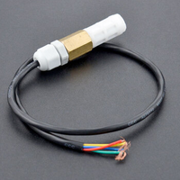
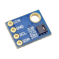
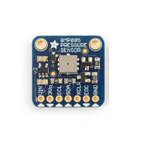
ESP32 HTE501 Temperature and Humidity Sensor
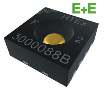
The E+E HTE501 is a digital humidity and temperature sensor designed for high accuracy in demanding environments. Compactly housed in a DFN package (2.5x2.5 mm), it offers ±1.8% RH and ±0.2 °C accuracy, and features a constant current heater and proprietary coating for stability.
🔗 Quick Links
ℹ️ About HTE501 Temperature and Humidity Sensor
The HTE501 is a high-precision digital humidity and temperature sensor, designed for accurate environmental monitoring. With fast response time and long-term stability, it is ideal for industrial, HVAC, and IoT applications.
⚡ Key Features #
- High Accuracy – Provides precise humidity and temperature measurements.
- Digital Output – Communicates via I²C for seamless integration.
- Fast Response & Stability – Reliable performance in dynamic environments.
- Compact & Energy-Efficient – Suitable for battery-powered applications.
The HTE501 is a great choice for climate control, smart home devices, and weather monitoring systems. 🚀
⚙️ HTE501 Sensor Technical Specifications
Below you can see the HTE501 Temperature and Humidity Sensor Technical Specifications. The sensor is compatible with the ESP32, operating within a voltage range suitable for microcontrollers. For precise details about its features, specifications, and usage, refer to the sensor’s datasheet.
- Type: environment
- Protocol: I2C
- Interface: I2C, 8-pin DFN
- Accuracy: ±1.8% RH, ±0.2 °C
- Operating Range: -40 to +135 °C, 0–100% RH
- Voltage: 2.35 – 3.60V
🔌 HTE501 Sensor Pinout
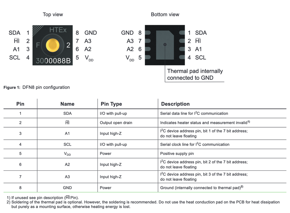
Below you can see the pinout for the HTE501 Temperature and Humidity Sensor. The VCC pin is used to supply power to the sensor, and it typically requires 3.3V or 5V (refer to the datasheet for specific voltage requirements). The GND pin is the ground connection and must be connected to the ground of your ESP32!
🧵 HTE501 Wiring with ESP32
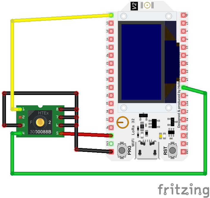
Below you can see the wiring for the HTE501 Temperature and Humidity Sensor with the ESP32. Connect the VCC pin of the sensor to the 3.3V pin on the ESP32 or external power supply for power and the GND pin of the sensor to the GND pin of the ESP32. Depending on the communication protocol of the sensor (e.g., I2C, SPI, UART, or analog), connect the appropriate data and clock or signal pins to compatible GPIO pins on the ESP32, as shown below in the wiring diagram.
🛠️ HTE501 Temperature and Humidity Sensor Troubleshooting
This guide outlines a systematic approach to troubleshoot and resolve common problems with the . Start by confirming that the hardware connections are correct, as wiring mistakes are the most frequent cause of issues. If you are sure the connections are correct, follow the below steps to debug common issues.
❌ Sensor Not Detected on I2C Bus
Issue: The HTE501 sensor is not recognized on the I2C bus, leading to communication failures.
Possible causes include incorrect wiring, improper I2C address configuration, or sensor malfunction.
Solution: Verify that the sensor's VCC and GND are properly connected to the power supply, and that SDA and SCL lines are correctly connected to the corresponding I2C pins on the microcontroller. Ensure that the I2C address matches the sensor's default or configured address. Use an I2C scanner to detect the sensor's presence on the bus. If the sensor remains undetected, consider testing with a different microcontroller or replacing the sensor.
⚠️ Incorrect or Unstable Readings
Issue: The HTE501 sensor provides temperature or humidity readings that are inaccurate or fluctuate unexpectedly.
Possible causes include environmental interference, improper sensor placement, or lack of calibration.
Solution: Place the sensor away from direct heat sources, sunlight, or areas with rapid temperature changes. Ensure that the sensor is properly initialized and calibrated in the code. If inaccuracies persist, consider implementing software-based calibration adjustments based on known reference values.
⏳ I2C Communication Timeouts
Issue: Communication with the HTE501 sensor over I2C results in timeout errors, especially during single-shot measurements.
Possible causes include the sensor's clock stretching behavior during measurements, which may not be properly handled by the microcontroller's I2C implementation.
Solution: Implement a delay (e.g., 20ms) after initiating a measurement to allow the sensor to process the data before attempting to read the results. Alternatively, monitor the sensor's status register to determine when the measurement is complete before reading the data. This approach ensures synchronization between the sensor and the microcontroller, preventing timeout errors.
💻Compilation Errors When Using HTE501 Library
Issue: Compilation errors occur when attempting to use the HTE501 sensor with a development platform.
Errors such as 'undefined reference' or 'no matching function' may appear.
Solution: Ensure that the correct library for the HTE501 sensor is installed and properly included in the project. Verify that the library version is compatible with your development environment. Check for any missing dependencies and ensure that all necessary files are present. If errors persist, consider consulting the library's documentation or seeking support from the developer community.
💻 Code Examples
Below you can find code examples of HTE501 Temperature and Humidity Sensor with ESP32 in several frameworks:
If you encounter issues while using the HTE501 Temperature and Humidity Sensor, check the Common Issues Troubleshooting Guide.

ESP32 HTE501 Arduino IDE Code Example
Fill in your main Arduino IDE sketch file with the following code to use the HTE501 Temperature and Humidity Sensor:
#include <Wire.h>
#include <Adafruit_SHT31.h> // Adafruit library compatible with I2C humidity/temp sensors

Adafruit_SHT31 sht31 = Adafruit_SHT31();

void setup() {
  Serial.begin(115200);        // Start the serial communication
  Wire.begin();                // Initialize I2C

  // Initialize the sensor
  if (!sht31.begin(0x44)) {    // The default I2C address for many SHT3x sensors is 0x44
    Serial.println("Couldn't find HTE501 sensor!");
    while (1) delay(1);        // Stop if the sensor is not found
  }
  Serial.println("HTE501 Sensor initialized.");
}

void loop() {
  float temperature = sht31.readTemperature();  // Read temperature in Celsius
  float humidity = sht31.readHumidity();        // Read relative humidity in %

  if (!isnan(temperature)) {                    // Check if reading is valid
    Serial.print("Temperature: ");
    Serial.print(temperature);
    Serial.println(" °C");
  } else {
    Serial.println("Error reading temperature.");
  }

  if (!isnan(humidity)) {                       // Check if reading is valid
    Serial.print("Humidity: ");
    Serial.print(humidity);
    Serial.println(" %");
  } else {
    Serial.println("Error reading humidity.");
  }

  delay(2000);                                  // Wait for 2 seconds before the next reading
}
This Arduino sketch uses the Adafruit SHT31 library to communicate with the HTE501 sensor via I2C. The setup() function initializes serial communication, the I2C bus, and the sensor. If the sensor initialization fails, an error message is printed, and the program halts. In the loop() function, temperature and humidity values are read using the library's methods, checked for validity, and then printed to the Serial Monitor. A 2-second delay ensures manageable update intervals.
Connect your ESP32 to your computer via a USB cable, Ensure the correct Board and Port are selected under Tools, Click the "Upload" button in the Arduino IDE to compile and upload the code to your ESP32.

ESP32 HTE501 ESP-IDF Code ExampleExample in Espressif IoT Framework (ESP-IDF)
If you're using ESP-IDF to work with the HTE501 Temperature and Humidity Sensor, here's how you can set it up and read data from the sensor. Fill in this code in the main ESP-IDF file:
#include <stdio.h>
#include "driver/i2c.h"
#include "esp_log.h"
#include "sdkconfig.h"

#define I2C_MASTER_SCL_IO 22               // GPIO number for I2C SCL
#define I2C_MASTER_SDA_IO 21               // GPIO number for I2C SDA
#define I2C_MASTER_NUM I2C_NUM_0           // I2C port number for master
#define I2C_MASTER_FREQ_HZ 100000          // I2C master clock frequency
#define I2C_MASTER_TX_BUF_DISABLE 0        // I2C master doesn't need buffer
#define I2C_MASTER_RX_BUF_DISABLE 0        // I2C master doesn't need buffer
#define HTE501_SENSOR_ADDR 0x44            // I2C address for the HTE501 sensor
#define HTE501_CMD_MEASURE 0x2C06          // Command for measurement

static const char *TAG = "HTE501";

void i2c_master_init() {
    i2c_config_t conf = {
        .mode = I2C_MODE_MASTER,
        .sda_io_num = I2C_MASTER_SDA_IO,
        .sda_pullup_en = GPIO_PULLUP_ENABLE,
        .scl_io_num = I2C_MASTER_SCL_IO,
        .scl_pullup_en = GPIO_PULLUP_ENABLE,
        .master.clk_speed = I2C_MASTER_FREQ_HZ,
    };
    i2c_param_config(I2C_MASTER_NUM, &conf);
    i2c_driver_install(I2C_MASTER_NUM, conf.mode, I2C_MASTER_RX_BUF_DISABLE, I2C_MASTER_TX_BUF_DISABLE, 0);
}

float read_humidity_temperature(float *temperature, float *humidity) {
    uint8_t data[6];
    i2c_cmd_handle_t cmd = i2c_cmd_link_create();
    i2c_master_start(cmd);
    i2c_master_write_byte(cmd, (HTE501_SENSOR_ADDR << 1) | I2C_MASTER_WRITE, true);
    i2c_master_write_byte(cmd, HTE501_CMD_MEASURE >> 8, true);
    i2c_master_write_byte(cmd, HTE501_CMD_MEASURE & 0xFF, true);
    i2c_master_stop(cmd);
    i2c_master_cmd_begin(I2C_MASTER_NUM, cmd, 1000 / portTICK_RATE_MS);
    i2c_cmd_link_delete(cmd);

    vTaskDelay(50 / portTICK_RATE_MS); // Wait for measurement

    cmd = i2c_cmd_link_create();
    i2c_master_start(cmd);
    i2c_master_write_byte(cmd, (HTE501_SENSOR_ADDR << 1) | I2C_MASTER_READ, true);
    i2c_master_read(cmd, data, 6, I2C_MASTER_LAST_NACK);
    i2c_master_stop(cmd);
    i2c_master_cmd_begin(I2C_MASTER_NUM, cmd, 1000 / portTICK_RATE_MS);
    i2c_cmd_link_delete(cmd);

    // Convert the data
    uint16_t raw_temp = (data[0] << 8) | data[1];
    uint16_t raw_hum = (data[3] << 8) | data[4];
    *temperature = -45 + 175 * ((float)raw_temp / 65535.0);
    *humidity = 100 * ((float)raw_hum / 65535.0);

    return ESP_OK;
}

void app_main() {
    i2c_master_init();
    float temperature, humidity;

    while (1) {
        if (read_humidity_temperature(&temperature, &humidity) == ESP_OK) {
            ESP_LOGI(TAG, "Temperature: %.2f °C", temperature);
            ESP_LOGI(TAG, "Humidity: %.2f %%", humidity);
        } else {
            ESP_LOGE(TAG, "Could not read from sensor");
        }
        vTaskDelay(2000 / portTICK_RATE_MS); // Delay for 2 seconds
    }
}
This ESP-IDF code sets up an I2C master to communicate with the HTE501 sensor on GPIO pins 21 (SDA) and 22 (SCL). The i2c_master_init() function configures and initializes the I2C interface. The read_humidity_temperature() function sends measurement commands to the sensor, retrieves the raw data, and converts it to temperature and humidity values using the sensor's scaling formulas. In the app_main() function, the temperature and humidity are read in an infinite loop and logged via ESP_LOG. A 2-second delay is added between readings.
Update the I2C pins (I2C_MASTER_SDA_IO and I2C_MASTER_SCL_IO) to match your ESP32 hardware setup, Use idf.py build to compile the project, Use idf.py flash to upload the code to your ESP32.

ESP32 HTE501 ESPHome Code Example
Fill in this configuration in your ESPHome YAML configuration file (example.yml) to integrate the HTE501 Temperature and Humidity Sensor
sensor:
  - platform: hte501
    temperature:
      name: "Office Temperature"
    humidity:
      name: "Office Humidity"
    address: 0x40
    update_interval: 60s
This ESPHome configuration defines a sensor platform for the HTE501. The platform key specifies the sensor type, and the I2C address is provided under the address key (e.g., 0x40). The temperature and humidity keys define the outputs with user-friendly names like 'Office Temperature' and 'Office Humidity.' The update_interval key ensures sensor readings are updated every 60 seconds.
Upload this code to your ESP32 using the ESPHome dashboard or the esphome run command.

ESP32 HTE501 PlatformIO Code Example
For PlatformIO, make sure to configure the platformio.ini file with the appropriate environment and libraries, and then proceed with the code.
Configure platformio.ini
First, your platformio.ini should look like below. You might need to include some libraries as shown. Make sure to change the board to your ESP32:
[env:esp32dev]
platform = espressif32
board = esp32dev
framework = espidf
monitor_speed = 115200

lib_deps =
    esp-idf-esp32
    Wire
ESP32 HTE501 PlatformIO Example Code
Write this code in your PlatformIO project under the src/main.cpp file to use the HTE501 Temperature and Humidity Sensor:
#include <stdio.h>
#include "driver/i2c.h"
#include "esp_log.h"

#define I2C_MASTER_SCL_IO 22               // GPIO number for I2C SCL
#define I2C_MASTER_SDA_IO 21               // GPIO number for I2C SDA
#define I2C_MASTER_NUM I2C_NUM_0           // I2C port number for master
#define I2C_MASTER_FREQ_HZ 100000          // I2C master clock frequency
#define I2C_MASTER_TX_BUF_DISABLE 0        // I2C master doesn't need buffer
#define I2C_MASTER_RX_BUF_DISABLE 0        // I2C master doesn't need buffer
#define HTE501_SENSOR_ADDR 0x44            // I2C address for the HTE501 sensor
#define HTE501_CMD_MEASURE 0x2C06          // Command for measurement

static const char *TAG = "HTE501";

void i2c_master_init() {
    i2c_config_t conf = {
        .mode = I2C_MODE_MASTER,
        .sda_io_num = I2C_MASTER_SDA_IO,
        .sda_pullup_en = GPIO_PULLUP_ENABLE,
        .scl_io_num = I2C_MASTER_SCL_IO,
        .scl_pullup_en = GPIO_PULLUP_ENABLE,
        .master.clk_speed = I2C_MASTER_FREQ_HZ,
    };
    i2c_param_config(I2C_MASTER_NUM, &conf);
    i2c_driver_install(I2C_MASTER_NUM, conf.mode, I2C_MASTER_RX_BUF_DISABLE, I2C_MASTER_TX_BUF_DISABLE, 0);
}

float read_humidity_temperature(float *temperature, float *humidity) {
    uint8_t data[6];
    i2c_cmd_handle_t cmd = i2c_cmd_link_create();
    i2c_master_start(cmd);
    i2c_master_write_byte(cmd, (HTE501_SENSOR_ADDR << 1) | I2C_MASTER_WRITE, true);
    i2c_master_write_byte(cmd, HTE501_CMD_MEASURE >> 8, true);
    i2c_master_write_byte(cmd, HTE501_CMD_MEASURE & 0xFF, true);
    i2c_master_stop(cmd);
    i2c_master_cmd_begin(I2C_MASTER_NUM, cmd, 1000 / portTICK_RATE_MS);
    i2c_cmd_link_delete(cmd);

    vTaskDelay(50 / portTICK_RATE_MS); // Wait for measurement

    cmd = i2c_cmd_link_create();
    i2c_master_start(cmd);
    i2c_master_write_byte(cmd, (HTE501_SENSOR_ADDR << 1) | I2C_MASTER_READ, true);
    i2c_master_read(cmd, data, 6, I2C_MASTER_LAST_NACK);
    i2c_master_stop(cmd);
    i2c_master_cmd_begin(I2C_MASTER_NUM, cmd, 1000 / portTICK_RATE_MS);
    i2c_cmd_link_delete(cmd);

    // Convert the data
    uint16_t raw_temp = (data[0] << 8) | data[1];
    uint16_t raw_hum = (data[3] << 8) | data[4];
    *temperature = -45 + 175 * ((float)raw_temp / 65535.0);
    *humidity = 100 * ((float)raw_hum / 65535.0);

    return ESP_OK;
}

void app_main() {
    i2c_master_init();
    float temperature, humidity;

    while (1) {
        if (read_humidity_temperature(&temperature, &humidity) == ESP_OK) {
            ESP_LOGI(TAG, "Temperature: %.2f °C", temperature);
            ESP_LOGI(TAG, "Humidity: %.2f %%", humidity);
        } else {
            ESP_LOGE(TAG, "Could not read from sensor");
        }
        vTaskDelay(2000 / portTICK_RATE_MS); // Delay for 2 seconds
    }
}
This PlatformIO ESP-IDF code initializes I2C communication to interface with the HTE501 sensor. The i2c_master_init() function configures the I2C master interface with GPIO pins 21 (SDA) and 22 (SCL). The read_humidity_temperature() function sends measurement commands to the HTE501, retrieves the raw sensor data, and calculates temperature and humidity using the sensor's conversion formulas. The app_main() function continuously reads and logs temperature and humidity values every 2 seconds.
Upload the code to your ESP32 using the PlatformIO "Upload" button in your IDE or the pio run --target upload command.
Conclusion
We went through technical specifications of HTE501 Temperature and Humidity Sensor, its pinout, connection with ESP32 and HTE501 Temperature and Humidity Sensor code examples with Arduino IDE, ESP-IDF, ESPHome and PlatformIO.

