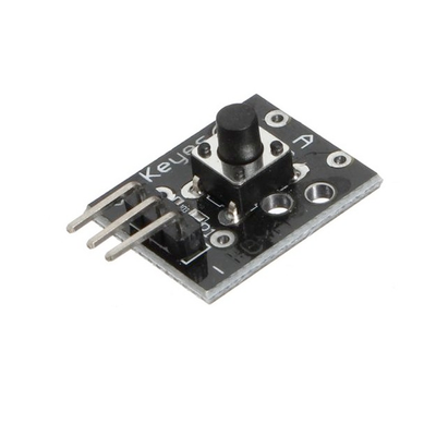
ESP32 KY-004 Key Switch Module
The KY-004 is a key switch module equipped with a tactile push-button. It provides a digital output signal when pressed, making it ideal for user input applications in various electronic projects.
⬇️ Jump to Code Examples


🔗 Quick Links


🛒 KY-004 Price


ℹ️ About KY-004 Key Switch Module
The KY-004 is a simple push-button switch module that provides digital input for microcontrollers. When pressed, it connects the signal pin to ground, sending a LOW signal to trigger an event. It operates within 3.3V to 5V, making it compatible with ESP32, Arduino, and other microcontrollers.
⚡ Key Features #
- Push-Button Activation – Sends a LOW signal when pressed.
- Operating Voltage – Works with 3.3V to 5V, ensuring broad compatibility.
- Simple Digital Output – Easy integration with ESP32, Arduino, and similar boards.
- Versatile Applications – Used for reset functions, menu navigation, and input controls.
With its compact design and easy-to-use interface, the KY-004 is perfect for user input, interactive devices, and control applications. 🚀
⚙️ KY-004 Sensor Technical Specifications
Below you can see the KY-004 Key Switch Module Technical Specifications. The sensor is compatible with the ESP32, operating within a voltage range suitable for microcontrollers. For precise details about its features, specifications, and usage, refer to the sensor’s datasheet.
- Type: module
- Protocol: Digital
- Operating Voltage: 3.3V to 5V
- Dimensions: 15mm x 26mm x 10mm
- Button Type: Tactile push-button
- Output Type: Digital signal
- Operating Temperature: -25°C to 105°C
- Durability: 100,000 cycles
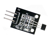
🔌 KY-004 Sensor Pinout
Below you can see the pinout for the KY-004 Key Switch Module. The VCC pin is used to supply power to the sensor, and it typically requires 3.3V or 5V (refer to the datasheet for specific voltage requirements). The GND pin is the ground connection and must be connected to the ground of your ESP32!
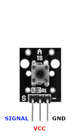
Pin (-):Connects to Ground (GND).Pin (+):Connects to VCC (3.3V or 5V).Pin (S):Outputs a digital signal when the button is pressed.
🧵 KY-004 Wiring with ESP32
Below you can see the wiring for the KY-004 Key Switch Module with the ESP32. Connect the VCC pin of the sensor to the 3.3V pin on the ESP32 or external power supply for power and the GND pin of the sensor to the GND pin of the ESP32. Depending on the communication protocol of the sensor (e.g., I2C, SPI, UART, or analog), connect the appropriate data and clock or signal pins to compatible GPIO pins on the ESP32, as shown below in the wiring diagram.
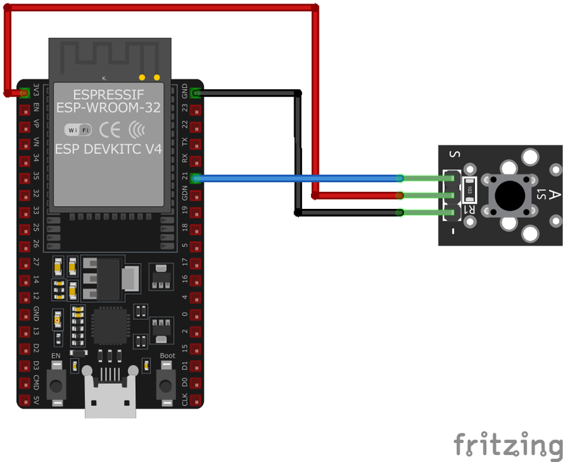
KY-004 Pin (-):Connect to ESP32GND.KY-004 Pin (+):Connect to ESP323.3Vor5V.KY-004 Pin (S):Connect to a GPIO pin on ESP32 (e.g.,GPIO4).
🛠️ KY-004 Key Switch Module Troubleshooting
This guide outlines a systematic approach to troubleshoot and resolve common problems with the . Start by confirming that the hardware connections are correct, as wiring mistakes are the most frequent cause of issues. If you are sure the connections are correct, follow the below steps to debug common issues.
❌ No Response from KY-004 Module
Issue: Pressing the button does not produce any response.
Solutions:
- Ensure all connections are secure and correctly placed.
- Verify that the module is receiving the appropriate voltage (3.3V or 5V).
- Check the microcontroller's GPIO pin configuration in the code.
- Test the module with a multimeter to confirm functionality.
⚠️ False Triggering of Button Press
Issue: The module sends signals without the button being pressed.
Solutions:
- Ensure that the pull-up resistor is properly connected and functioning.
- Implement software debouncing to filter out spurious signals.
- Check for any short circuits or loose connections on the module.
💻 Code Examples
Below you can find code examples of KY-004 Key Switch Module with ESP32 in several frameworks:
If you encounter issues while using the KY-004 Key Switch Module, check the Common Issues Troubleshooting Guide.

ESP32 KY-004 Arduino IDE Code Example
Fill in your main Arduino IDE sketch file with the following code to use the KY-004 Key Switch Module:
#define BUTTON_PIN 7
#define LED_PIN 13

void setup() {
    pinMode(BUTTON_PIN, INPUT);
    digitalWrite(BUTTON_PIN, HIGH); // Enable internal pull-up resistor
    pinMode(LED_PIN, OUTPUT);
    Serial.begin(9600);
    Serial.println("KY-004 Key Switch Module Test");
}

void loop() {
    int buttonState = digitalRead(BUTTON_PIN);
    if (buttonState == LOW) {
        Serial.println("Button pressed");
        digitalWrite(LED_PIN, HIGH);
    } else {
        Serial.println("Button released");
        digitalWrite(LED_PIN, LOW);
    }
    delay(100);
}
This Arduino code sets up the KY-004 Key Switch Module on pin 7 and an LED on pin 13. When the button is pressed, the sensor outputs a LOW signal, turning on the LED and printing a message to the serial monitor.
Connect your ESP32 to your computer via a USB cable, Ensure the correct Board and Port are selected under Tools, Click the "Upload" button in the Arduino IDE to compile and upload the code to your ESP32.

ESP32 KY-004 ESP-IDF Code ExampleExample in Espressif IoT Framework (ESP-IDF)
If you're using ESP-IDF to work with the KY-004 Key Switch Module, here's how you can set it up and read data from the sensor. Fill in this code in the main ESP-IDF file:
#include <stdio.h>
#include "freertos/FreeRTOS.h"
#include "freertos/task.h"
#include "driver/gpio.h"

#define BUTTON_PIN GPIO_NUM_4
#define LED_PIN GPIO_NUM_2

void app_main(void) {
    gpio_set_direction(BUTTON_PIN, GPIO_MODE_INPUT);
    gpio_set_pull_mode(BUTTON_PIN, GPIO_PULLUP_ONLY);
    gpio_set_direction(LED_PIN, GPIO_MODE_OUTPUT);
    printf("KY-004 Key Switch Module Test\n");
    while (1) {
        int button_state = gpio_get_level(BUTTON_PIN);
        if (button_state == 0) {
            printf("Button pressed\n");
            gpio_set_level(LED_PIN, 1);
        } else {
            printf("Button released\n");
            gpio_set_level(LED_PIN, 0);
        }
        vTaskDelay(pdMS_TO_TICKS(100));
    }
}
This ESP-IDF code configures GPIO4 as an input for the KY-004 Key Switch Module and GPIO2 as an output for an LED. When the button is pressed (sensor outputs LOW), the LED turns on, and a message is printed to the console.
Update the I2C pins (I2C_MASTER_SDA_IO and I2C_MASTER_SCL_IO) to match your ESP32 hardware setup, Use idf.py build to compile the project, Use idf.py flash to upload the code to your ESP32.
ESP32 KY-004 ESPHome Code Example
Fill in this configuration in your ESPHome YAML configuration file (example.yml) to integrate the KY-004 Key Switch Module
binary_sensor:
  - platform: gpio
    pin:
      number: GPIO4
      mode: INPUT_PULLUP
    name: "KY-004 Key Switch"
    filters:
      - delayed_on: 10ms
      - delayed_off: 10ms
    on_press:
      - then:
          - lambda: |-
              ESP_LOGD("sensor", "Button pressed!");
This ESPHome configuration sets up the KY-004 Key Switch as a binary sensor on GPIO4 with an internal pull-up resistor. It includes filtering to debounce false triggers and logs when the button is pressed.
Upload this code to your ESP32 using the ESPHome dashboard or the esphome run command.

ESP32 KY-004 PlatformIO Code Example
For PlatformIO, make sure to configure the platformio.ini file with the appropriate environment and libraries, and then proceed with the code.
Configure platformio.ini
First, your platformio.ini should look like below. You might need to include some libraries as shown. Make sure to change the board to your ESP32:
[env:esp32]
platform = espressif32
board = esp32dev
framework = arduino
ESP32 KY-004 PlatformIO Example Code
Write this code in your PlatformIO project under the src/main.cpp file to use the KY-004 Key Switch Module:
#include <Arduino.h>

#define BUTTON_PIN 4
#define LED_PIN 2

void setup() {
    pinMode(BUTTON_PIN, INPUT_PULLUP);
    pinMode(LED_PIN, OUTPUT);
    Serial.begin(115200);
    Serial.println("KY-004 Key Switch Module Test");
}

void loop() {
    if (digitalRead(BUTTON_PIN) == LOW) {
        Serial.println("Button pressed");
        digitalWrite(LED_PIN, HIGH);
    } else {
        Serial.println("Button released");
        digitalWrite(LED_PIN, LOW);
    }
    delay(100);
}
This PlatformIO code configures the KY-004 Key Switch on GPIO4 and an LED on GPIO2. When the button is pressed, the LED turns on, and a message is printed to the serial monitor.
Upload the code to your ESP32 using the PlatformIO "Upload" button in your IDE or the pio run --target upload command.

ESP32 KY-004 MicroPython Code Example
Fill in this script in your MicroPython main.py file (main.py) to integrate the KY-004 Key Switch Module with your ESP32.
import machine
import time

BUTTON_PIN = machine.Pin(4, machine.Pin.IN, machine.Pin.PULL_UP)
LED_PIN = machine.Pin(2, machine.Pin.OUT)

while True:
    if BUTTON_PIN.value() == 0:
        print("Button pressed")
        LED_PIN.on()
    else:
        print("Button released")
        LED_PIN.off()
    time.sleep(0.1)
This MicroPython script configures the KY-004 Key Switch on GPIO4 and an LED on GPIO2. When the button is pressed (LOW signal), the LED turns on, and a message is printed to the console.
Upload this code to your ESP32 using a MicroPython-compatible IDE, such as Thonny, uPyCraft, or tools like ampy.
Conclusion
We went through technical specifications of KY-004 Key Switch Module, its pinout, connection with ESP32 and KY-004 Key Switch Module code examples with Arduino IDE, ESP-IDF, ESPHome and PlatformIO.