ESP32 KY-010 Photo Interrupter Module
Overview
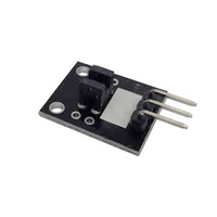
The KY-010 is a photo interrupter module that detects objects by sensing interruptions in an infrared beam. It's ideal for applications requiring non-contact object detection, such as counting or speed measurement.


About KY-010 Photo Interrupter Module
The KY-010 Photo Interrupter Module is a digital sensor that detects the presence or absence of an object within its slot. It consists of an infrared emitter and receiver facing each other, forming a light barrier. When an object passes through the slot, it interrupts the infrared beam, causing a change in the output signal. This module operates at a voltage range of 3.3V to 5V, making it compatible with various microcontrollers such as Arduino and ESP32. It’s commonly used in applications like object counting, edge detection, and motor speed measurement.
Where to Buy

Starting from
1$ per unit


Prices are subject to change. We earn from qualifying purchases as an Amazon Associate.
Technical Specifications
Pinout Configuration
The VCC pin is used to supply power to the sensor, and it typically requires 3.3V or 5V (refer to the datasheet for specific voltage requirements). The GND pin is the ground connection and must be connected to the ground of your ESP32.

Pin (-):Ground (GND).Pin (+):Power supply (VCC), typically 3.3V or 5V.Pin (S):Digital output signal.
Wiring with ESP32
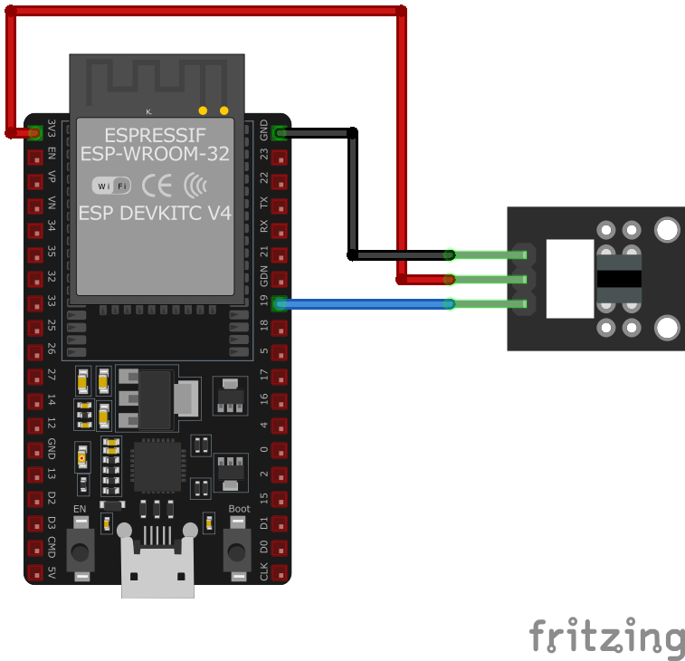
KY-010 Pin (-):Connect to ESP32GND.KY-010 Pin (+):Connect to ESP323.3Vor5V.KY-010 Pin (S):Connect to a digital GPIO pin on ESP32 (e.g.,GPIO15).
Troubleshooting Guide
Common Issues
❌ No Signal Detection
Issue: The module does not detect any object passing through the slot.
Solutions:
- Ensure the module is properly powered with the correct voltage.
- Verify that the signal pin is correctly connected to the microcontroller's GPIO pin.
- Check for any obstructions or debris within the slot that could affect detection.
⚠️ False Triggering
Issue: The module outputs signals without any object present.
Solutions:
- Ensure there is no ambient infrared light interfering with the sensor.
- Check for loose connections or unstable power supply.
- Verify that the microcontroller's input pin is properly configured with pull-up or pull-down resistors as needed.
Debugging Tips
🔍 Serial Monitor
Use the Serial Monitor to check for error messages and verify the sensor's output. Add debug prints in your code to track the sensor's state.
⚡ Voltage Checks
Use a multimeter to verify voltage levels and check for continuity in your connections. Ensure the power supply is stable and within the sensor's requirements.
Additional Resources
Code Examples
Arduino Example
int sensorPin = 10; // Sensor connected to digital pin 10
int ledPin = 13;    // LED connected to digital pin 13
int sensorValue = 0;

void setup() {
    pinMode(ledPin, OUTPUT);
    pinMode(sensorPin, INPUT);
    digitalWrite(sensorPin, HIGH); // Enable internal pull-up resistor
    Serial.begin(9600);
}

void loop() {
    sensorValue = digitalRead(sensorPin);
    if (sensorValue == HIGH) {
        digitalWrite(ledPin, HIGH); // Turn on LED
        Serial.println("Object detected");
    } else {
        digitalWrite(ledPin, LOW); // Turn off LED
    }
    delay(100);
}
This Arduino code sets up the KY-010 sensor on digital pin 10 and an LED on pin 13. The internal pull-up resistor is enabled for the sensor pin. When an object interrupts the sensor's beam, the LED lights up, and a message is printed to the serial monitor.
ESP-IDF Example
#include <stdio.h>
#include "freertos/FreeRTOS.h"
#include "freertos/task.h"
#include "driver/gpio.h"

#define SENSOR_PIN GPIO_NUM_15
#define LED_PIN GPIO_NUM_2

void app_main(void) {
    // Configure sensor pin as input with pull-up resistor
    gpio_config_t sensor_io_conf = {
        .pin_bit_mask = (1ULL << SENSOR_PIN),
        .mode = GPIO_MODE_INPUT,
        .pull_up_en = GPIO_PULLUP_ENABLE,
        .pull_down_en = GPIO_PULLDOWN_DISABLE,
        .intr_type = GPIO_INTR_DISABLE
    };
    gpio_config(&sensor_io_conf);

    // Configure LED pin as output
    gpio_config_t led_io_conf = {
        .pin_bit_mask = (1ULL << LED_PIN),
        .mode = GPIO_MODE_OUTPUT,
        .pull_up_en = GPIO_PULLUP_DISABLE,
        .pull_down_en = GPIO_PULLDOWN_DISABLE,
        .intr_type = GPIO_INTR_DISABLE
    };
    gpio_config(&led_io_conf);

    printf("KY-010 Photo Interrupter Module Test\n");

    while (1) {
        int sensor_value = gpio_get_level(SENSOR_PIN);
        if (sensor_value == 1) {
            gpio_set_level(LED_PIN, 1); // Turn on LED
            printf("Object detected\n");
        } else {
            gpio_set_level(LED_PIN, 0); // Turn off LED
        }
        vTaskDelay(pdMS_TO_TICKS(100));
    }
}
This ESP-IDF code configures the KY-010 Photo Interrupter Module on GPIO15 and an LED on GPIO2. The sensor pin is set up as an input with an internal pull-up resistor, while the LED pin is configured as an output. The main loop continuously checks if an object interrupts the infrared beam. If an object is detected, the LED turns on, and a message is printed to the console.
ESPHome Example
binary_sensor:
  - platform: gpio
    pin:
      number: GPIO15
      mode: INPUT_PULLUP
    name: "KY-010 Object Detector"
    filters:
      - delayed_on: 10ms
      - delayed_off: 10ms
    on_press:
      - then:
          - lambda: |-
              ESP_LOGD("sensor", "Object detected!");
This ESPHome configuration sets up the KY-010 Photo Interrupter Module as a binary sensor on GPIO15 with an internal pull-up resistor. It applies filtering to debounce false triggers and logs when an object is detected.
PlatformIO Example
platformio.ini
[env:esp32]
platform = espressif32
board = esp32dev
framework = arduino
PlatformIO Example Code
#include <Arduino.h>

#define SENSOR_PIN 15
#define LED_PIN 2

void setup() {
    pinMode(SENSOR_PIN, INPUT_PULLUP);
    pinMode(LED_PIN, OUTPUT);
    Serial.begin(115200);
    Serial.println("KY-010 Photo Interrupter Module Test");
}

void loop() {
    if (digitalRead(SENSOR_PIN) == HIGH) {
        Serial.println("Object detected");
        digitalWrite(LED_PIN, HIGH);
    } else {
        digitalWrite(LED_PIN, LOW);
    }
    delay(100);
}
This PlatformIO code configures the KY-010 sensor on GPIO15 and an LED on GPIO2. When an object interrupts the infrared beam, the LED turns on, and a message is printed to the serial monitor.
MicroPython Example
import machine
import time

SENSOR_PIN = machine.Pin(15, machine.Pin.IN, machine.Pin.PULL_UP)
LED_PIN = machine.Pin(2, machine.Pin.OUT)

while True:
    if SENSOR_PIN.value() == 1:
        print("Object detected")
        LED_PIN.on()
    else:
        LED_PIN.off()
    time.sleep(0.1)
This MicroPython script configures the KY-010 Photo Interrupter Module on GPIO15 and an LED on GPIO2. When an object interrupts the sensor's beam, the LED turns on, and a message is printed to the console.
Conclusion
The ESP32 KY-010 Photo Interrupter Module is a powerful KY-0xx module sensor that offers excellent performance and reliability. With support for multiple development platforms including Arduino, ESP-IDF, ESPHome, PlatformIO, and MicroPython, it's a versatile choice for your IoT projects.
For optimal performance, ensure proper wiring and follow the recommended configuration for your chosen development platform.
Always verify power supply requirements and pin connections before powering up your project to avoid potential damage.