ESP32 KY-018 Photoresistor Module
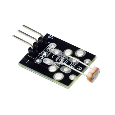
The KY-018 is a photoresistor module that detects ambient light levels. It outputs an analog signal corresponding to the light intensity, making it suitable for projects that require light sensing capabilities.
⬇️ Jump to Code Examples


🔗 Quick Links


🛒 KY-018 Price


ℹ️ About KY-018 Photoresistor Module
The KY-018 Photoresistor Module is a light-sensitive sensor that varies its resistance based on the ambient light intensity. It contains a light-dependent resistor (LDR) and a fixed 10 kΩ resistor, forming a voltage divider circuit. As the surrounding light increases, the LDR's resistance decreases, resulting in a higher output voltage. This module operates at a voltage range of 3.3V to 5V and provides an analog output signal. It's commonly used in applications such as ambient light detection, automatic lighting control, and light intensity measurement.⚙️ KY-018 Sensor Technical Specifications
Below you can see the KY-018 Photoresistor Module Technical Specifications. The sensor is compatible with the ESP32, operating within a voltage range suitable for microcontrollers. For precise details about its features, specifications, and usage, refer to the sensor’s datasheet.
- Protocol: Analog
- Operating Voltage: 3.3V - 5V
- Output Type: Analog
- Fixed Resistor Value: 10 kΩ
- Dimensions: 21 x 15 x 6 mm
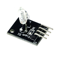
🔌 KY-018 Sensor Pinout
Below you can see the pinout for the KY-018 Photoresistor Module. The VCC pin is used to supply power to the sensor, and it typically requires 3.3V or 5V (refer to the datasheet for specific voltage requirements). The GND pin is the ground connection and must be connected to the ground of your ESP32!
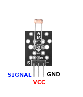
Pin (-):Connects to ground (GND).Pin (middle):Connects to VCC (3.3V to 5V).Pin (S):Outputs the analog signal; connect to an analog input on your microcontroller.
🧵 KY-018 Wiring with ESP32
Below you can see the wiring for the KY-018 Photoresistor Module with the ESP32. Connect the VCC pin of the sensor to the 3.3V pin on the ESP32 or external power supply for power and the GND pin of the sensor to the GND pin of the ESP32. Depending on the communication protocol of the sensor (e.g., I2C, SPI, UART, or analog), connect the appropriate data and clock or signal pins to compatible GPIO pins on the ESP32, as shown below in the wiring diagram.
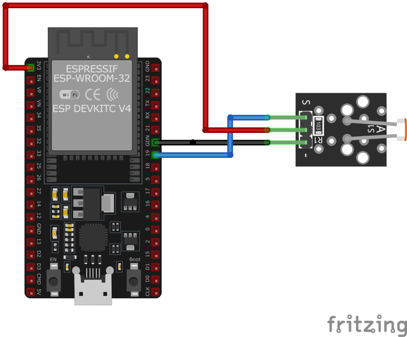
KY-018 Pin (-):Connect to ESP32GND.KY-018 Pin (middle):Connect to ESP323.3Vor5V.KY-018 Pin (S):Connect to an analog GPIO pin on ESP32 (e.g.,GPIO36).
🛠️ KY-018 Photoresistor Module Troubleshooting
This guide outlines a systematic approach to troubleshoot and resolve common problems with the . Start by confirming that the hardware connections are correct, as wiring mistakes are the most frequent cause of issues. If you are sure the connections are correct, follow the below steps to debug common issues.
❌ No Response from Sensor
Issue: The sensor does not output any signal regardless of light conditions.
Solutions:
- Verify that all connections are secure and correctly placed.
- Ensure the module is receiving the appropriate voltage (3.3V to 5V).
- Check if the microcontroller's analog input pin is correctly configured.
⚠️ Incorrect or Fluctuating Readings
Issue: The sensor outputs inconsistent or incorrect light intensity values.
Solutions:
- Ensure stable lighting conditions during measurements.
- Check for loose connections or interference from nearby electronic components.
- Implement software filtering to smooth out rapid fluctuations in readings.
💻 Code Examples
Below you can find code examples of KY-018 Photoresistor Module with ESP32 in several frameworks:
If you encounter issues while using the KY-018 Photoresistor Module, check the Common Issues Troubleshooting Guide.

ESP32 KY-018 Arduino IDE Code Example
Fill in your main Arduino IDE sketch file with the following code to use the KY-018 Photoresistor Module:
int sensorPin = A0; // Photoresistor connected to analog pin A0
int sensorValue = 0;

void setup() {
    Serial.begin(9600);
    Serial.println("KY-018 Photoresistor Test");
}

void loop() {
    sensorValue = analogRead(sensorPin);
    Serial.print("Light Intensity: ");
    Serial.println(sensorValue);
    delay(500);
}
This Arduino code sets up the KY-018 photoresistor on analog pin A0. It reads the analog value corresponding to the light intensity and prints it to the serial monitor every 500 milliseconds.
Connect your ESP32 to your computer via a USB cable, Ensure the correct Board and Port are selected under Tools, Click the "Upload" button in the Arduino IDE to compile and upload the code to your ESP32.
ESP32 KY-018 ESP-IDF Code ExampleExample in Espressif IoT Framework (ESP-IDF)
If you're using ESP-IDF to work with the KY-018 Photoresistor Module, here's how you can set it up and read data from the sensor. Fill in this code in the main ESP-IDF file:
#include <stdio.h>
#include "freertos/FreeRTOS.h"
#include "freertos/task.h"
#include "driver/adc.h"

#define PHOTORESISTOR_CHANNEL ADC1_CHANNEL_0 // GPIO36

void app_main(void) {
    adc1_config_width(ADC_WIDTH_BIT_12);
    adc1_config_channel_atten(PHOTORESISTOR_CHANNEL, ADC_ATTEN_DB_0);

    printf("KY-018 Photoresistor Test\n");

    while (1) {
        int raw = adc1_get_raw(PHOTORESISTOR_CHANNEL);
        printf("Light Intensity: %d\n", raw);
        vTaskDelay(pdMS_TO_TICKS(500));
    }
}
This ESP-IDF code configures GPIO36 (ADC1_CHANNEL_0) to read analog values from the KY-018 photoresistor. It prints the raw ADC value, corresponding to light intensity, to the console every 500 milliseconds.
Update the I2C pins (I2C_MASTER_SDA_IO and I2C_MASTER_SCL_IO) to match your ESP32 hardware setup, Use idf.py build to compile the project, Use idf.py flash to upload the code to your ESP32.
ESP32 KY-018 ESPHome Code Example
Fill in this configuration in your ESPHome YAML configuration file (example.yml) to integrate the KY-018 Photoresistor Module
sensor:
  - platform: adc
    pin: GPIO36
    name: "KY-018 Light Intensity"
    update_interval: 500ms
    filters:
      - multiply: 0.00322265625
This ESPHome configuration sets up the KY-018 photoresistor on GPIO36. It reads the analog value every 500 milliseconds and applies a multiplier to convert the raw ADC reading to a voltage value.
Upload this code to your ESP32 using the ESPHome dashboard or the esphome run command.

ESP32 KY-018 PlatformIO Code Example
For PlatformIO, make sure to configure the platformio.ini file with the appropriate environment and libraries, and then proceed with the code.
Configure platformio.ini
First, your platformio.ini should look like below. You might need to include some libraries as shown. Make sure to change the board to your ESP32:
[env:esp32]
platform = espressif32
board = esp32dev
framework = arduino
ESP32 KY-018 PlatformIO Example Code
Write this code in your PlatformIO project under the src/main.cpp file to use the KY-018 Photoresistor Module:
#include <Arduino.h>

#define PHOTORESISTOR_PIN 36

void setup() {
    Serial.begin(115200);
    Serial.println("KY-018 Photoresistor Test");
}

void loop() {
    int sensorValue = analogRead(PHOTORESISTOR_PIN);
    Serial.print("Light Intensity: ");
    Serial.println(sensorValue);
    delay(500);
}
This PlatformIO code configures GPIO36 as an analog input to read the KY-018 photoresistor sensor values. The light intensity readings are printed to the serial monitor every 500 milliseconds.
Upload the code to your ESP32 using the PlatformIO "Upload" button in your IDE or the pio run --target upload command.

ESP32 KY-018 MicroPython Code Example
Fill in this script in your MicroPython main.py file (main.py) to integrate the KY-018 Photoresistor Module with your ESP32.
import machine
import time

PHOTORESISTOR_PIN = 36  # ADC input pin
adc = machine.ADC(machine.Pin(PHOTORESISTOR_PIN))
adc.atten(machine.ADC.ATTN_11DB)  # Full range 0-3.3V

while True:
    light_intensity = adc.read()
    print("Light Intensity:", light_intensity)
    time.sleep(0.5)
This MicroPython script configures GPIO36 as an ADC input for the KY-018 photoresistor sensor. The sensor value is read every 500 milliseconds and printed to the console.
Upload this code to your ESP32 using a MicroPython-compatible IDE, such as Thonny, uPyCraft, or tools like ampy.
Conclusion
We went through technical specifications of KY-018 Photoresistor Module, its pinout, connection with ESP32 and KY-018 Photoresistor Module code examples with Arduino IDE, ESP-IDF, ESPHome and PlatformIO.