ESP32 KY-023 Dual Axis Joystick Module
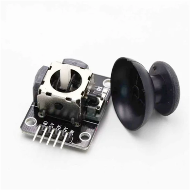
The KY-023 is a dual-axis joystick module that provides analog outputs for X and Y positions, along with a digital output for a built-in push-button. It's ideal for applications requiring directional input, such as remote controls, gaming interfaces, and robotic navigation.
⬇️ Jump to Code Examples


🔗 Quick Links


🛒 KY-023 Price


ℹ️ About KY-023 Dual Axis Joystick Module
The KY-023 Dual Axis Joystick Module is an input device that combines two potentiometers and a push-button switch, allowing for control in both the X and Y axes. Each axis corresponds to a potentiometer that outputs an analog voltage, which can be read by microcontrollers like the Arduino or ESP32. The module also features a push-button that activates when the joystick is pressed down. This joystick is commonly used in robotics, gaming, and other interactive projects.⚙️ KY-023 Sensor Technical Specifications
Below you can see the KY-023 Dual Axis Joystick Module Technical Specifications. The sensor is compatible with the ESP32, operating within a voltage range suitable for microcontrollers. For precise details about its features, specifications, and usage, refer to the sensor’s datasheet.
- Type: module
- Protocol: Analog
- Operating Voltage: 3.3V - 5V
- Output Voltage Range: 0V to VCC
- Dimensions: 34 x 39 x 26 mm
- Weight: 12 g
🔌 KY-023 Sensor Pinout
Below you can see the pinout for the KY-023 Dual Axis Joystick Module. The VCC pin is used to supply power to the sensor, and it typically requires 3.3V or 5V (refer to the datasheet for specific voltage requirements). The GND pin is the ground connection and must be connected to the ground of your ESP32!
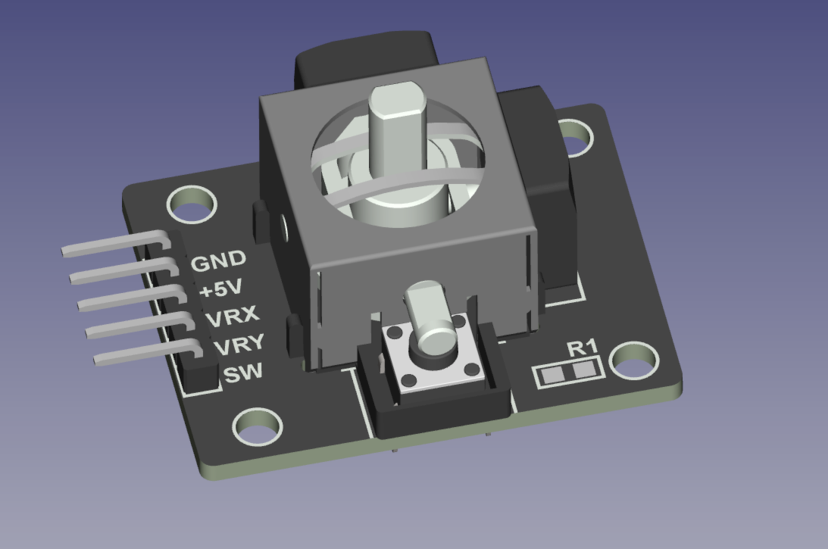
GND:Connects to ground.+5V:Connects to 5V power supply.VRx:Outputs analog voltage corresponding to X-axis position.VRy:Outputs analog voltage corresponding to Y-axis position.SW:Digital output for the push-button; active low when pressed.
🧵 KY-023 Wiring with ESP32
Below you can see the wiring for the KY-023 Dual Axis Joystick Module with the ESP32. Connect the VCC pin of the sensor to the 3.3V pin on the ESP32 or external power supply for power and the GND pin of the sensor to the GND pin of the ESP32. Depending on the communication protocol of the sensor (e.g., I2C, SPI, UART, or analog), connect the appropriate data and clock or signal pins to compatible GPIO pins on the ESP32, as shown below in the wiring diagram.
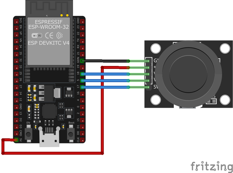
GND:Connect to ESP32GND.+5V:Connect to ESP323.3Vor5V(ensure voltage compatibility).VRx:Connect to an analog input pin on ESP32 (e.g.,GPIO36).VRy:Connect to another analog input pin on ESP32 (e.g.,GPIO39).SW:Connect to a digital input pin on ESP32 (e.g.,GPIO34); configure with an internal pull-up resistor.
🛠️ KY-023 Dual Axis Joystick Module Troubleshooting
This guide outlines a systematic approach to troubleshoot and resolve common problems with the . Start by confirming that the hardware connections are correct, as wiring mistakes are the most frequent cause of issues. If you are sure the connections are correct, follow the below steps to debug common issues.
❌ Joystick Not Responding
Issue: No change in analog readings when moving the joystick.
Solutions:
- Verify all connections are secure and correctly placed.
- Ensure the module is receiving the appropriate voltage (3.3V or 5V).
- Check that the microcontroller's analog input pins are correctly configured.
- Test the joystick with a multimeter to confirm the potentiometers are functioning.
❓ Button Not Registering Presses
Issue: The push-button does not trigger any response.
Solutions:
- Ensure the SW pin is connected to a digital input configured with a pull-up resistor.
- Check for continuity in the button circuit using a multimeter.
- Confirm that the microcontroller's digital input pin is correctly configured in the code.
💻 Code Examples
Below you can find code examples of KY-023 Dual Axis Joystick Module with ESP32 in several frameworks:
If you encounter issues while using the KY-023 Dual Axis Joystick Module, check the Common Issues Troubleshooting Guide.

ESP32 KY-023 Arduino IDE Code Example
Fill in your main Arduino IDE sketch file with the following code to use the KY-023 Dual Axis Joystick Module:
// Declaration and initialization of the input pins
int JoyStick_X = A0; // X-axis signal
int JoyStick_Y = A1; // Y-axis signal
int Button = 3; // Button

void setup() {
    pinMode(JoyStick_X, INPUT);
    pinMode(JoyStick_Y, INPUT);
    pinMode(Button, INPUT_PULLUP); // Enable internal pull-up resistor
    Serial.begin(9600); // Serial output with 9600 bps
}

void loop() {
    float x, y;
    int buttonState;
    // Read current values and convert to voltage
    x = analogRead(JoyStick_X) * (5.0 / 1023.0);
    y = analogRead(JoyStick_Y) * (5.0 / 1023.0);
    buttonState = digitalRead(Button);
    // Output the values
    Serial.print("X-axis:"); Serial.print(x, 4); Serial.print("V, ");
    Serial.print("Y-axis:"); Serial.print(y, 4); Serial.print("V, ");
    Serial.print("Button:");
    if (buttonState == HIGH) {
        Serial.println("not pressed");
    } else {
        Serial.println("pressed");
    }
    delay(200);
}
This Arduino code reads the analog values from the X and Y axes of the KY-023 joystick and the digital state of the push-button. It then prints the corresponding voltage levels and button state to the serial monitor.
Connect your ESP32 to your computer via a USB cable, Ensure the correct Board and Port are selected under Tools, Click the "Upload" button in the Arduino IDE to compile and upload the code to your ESP32.

ESP32 KY-023 ESP-IDF Code ExampleExample in Espressif IoT Framework (ESP-IDF)
If you're using ESP-IDF to work with the KY-023 Dual Axis Joystick Module, here's how you can set it up and read data from the sensor. Fill in this code in the main ESP-IDF file:
#include <stdio.h>
#include "freertos/FreeRTOS.h"
#include "freertos/task.h"
#include "driver/adc.h"
#include "driver/gpio.h"

#define JOYSTICK_X ADC1_CHANNEL_0 // GPIO36
#define JOYSTICK_Y ADC1_CHANNEL_3 // GPIO39
#define BUTTON GPIO_NUM_34

void app_main(void) {
    adc1_config_width(ADC_WIDTH_BIT_12);
    adc1_config_channel_atten(JOYSTICK_X, ADC_ATTEN_DB_11);
    adc1_config_channel_atten(JOYSTICK_Y, ADC_ATTEN_DB_11);
    gpio_set_direction(BUTTON, GPIO_MODE_INPUT);
    gpio_pulldown_en(BUTTON);

    printf("KY-023 Joystick Test\n");
    while (1) {
        int x_value = adc1_get_raw(JOYSTICK_X);
        int y_value = adc1_get_raw(JOYSTICK_Y);
        int button_state = gpio_get_level(BUTTON);
        printf("X: %d, Y: %d, Button: %s\n", x_value, y_value, button_state ? "Not Pressed" : "Pressed");
        vTaskDelay(pdMS_TO_TICKS(200));
    }
}
This ESP-IDF code reads analog values from the KY-023 joystick's X and Y axes using ADC1 on GPIO36 and GPIO39. It also monitors the push-button state on GPIO34 and prints the readings to the console every 200ms.
Update the I2C pins (I2C_MASTER_SDA_IO and I2C_MASTER_SCL_IO) to match your ESP32 hardware setup, Use idf.py build to compile the project, Use idf.py flash to upload the code to your ESP32.

ESP32 KY-023 ESPHome Code Example
Fill in this configuration in your ESPHome YAML configuration file (example.yml) to integrate the KY-023 Dual Axis Joystick Module
sensor:
  - platform: adc
    pin: GPIO36
    name: "KY-023 Joystick X-Axis"
    update_interval: 200ms
  - platform: adc
    pin: GPIO39
    name: "KY-023 Joystick Y-Axis"
    update_interval: 200ms
binary_sensor:
  - platform: gpio
    pin:
      number: GPIO34
      mode: INPUT_PULLUP
    name: "KY-023 Joystick Button"
This ESPHome configuration sets up the KY-023 joystick module on ESP32. It reads the X and Y-axis values as analog inputs and detects button presses on GPIO34, logging the results every 200ms.
Upload this code to your ESP32 using the ESPHome dashboard or the esphome run command.

ESP32 KY-023 PlatformIO Code Example
For PlatformIO, make sure to configure the platformio.ini file with the appropriate environment and libraries, and then proceed with the code.
Configure platformio.ini
First, your platformio.ini should look like below. You might need to include some libraries as shown. Make sure to change the board to your ESP32:
[env:esp32]
platform = espressif32
board = esp32dev
framework = arduino
ESP32 KY-023 PlatformIO Example Code
Write this code in your PlatformIO project under the src/main.cpp file to use the KY-023 Dual Axis Joystick Module:
#include <Arduino.h>

#define JOYSTICK_X A0
#define JOYSTICK_Y A1
#define BUTTON 3

void setup() {
    pinMode(JOYSTICK_X, INPUT);
    pinMode(JOYSTICK_Y, INPUT);
    pinMode(BUTTON, INPUT_PULLUP);
    Serial.begin(115200);
    Serial.println("KY-023 Joystick Module Test");
}

void loop() {
    int x_value = analogRead(JOYSTICK_X);
    int y_value = analogRead(JOYSTICK_Y);
    int button_state = digitalRead(BUTTON);
    Serial.printf("X: %d, Y: %d, Button: %s\n", x_value, y_value, button_state ? "Not Pressed" : "Pressed");
    delay(200);
}
This PlatformIO code reads the analog values of the KY-023 joystick's X and Y axes and detects button presses. It prints the readings to the serial monitor every 200ms.
Upload the code to your ESP32 using the PlatformIO "Upload" button in your IDE or the pio run --target upload command.

ESP32 KY-023 MicroPython Code Example
Fill in this script in your MicroPython main.py file (main.py) to integrate the KY-023 Dual Axis Joystick Module with your ESP32.
import machine
import time

JOYSTICK_X = machine.ADC(machine.Pin(36))
JOYSTICK_Y = machine.ADC(machine.Pin(39))
BUTTON = machine.Pin(34, machine.Pin.IN, machine.Pin.PULL_UP)

JOYSTICK_X.atten(machine.ADC.ATTN_11DB)
JOYSTICK_Y.atten(machine.ADC.ATTN_11DB)

while True:
    x_value = JOYSTICK_X.read()
    y_value = JOYSTICK_Y.read()
    button_state = BUTTON.value()
    print("X:", x_value, "Y:", y_value, "Button:", "Not Pressed" if button_state else "Pressed")
    time.sleep(0.2)
This MicroPython script reads the analog values of the KY-023 joystick's X and Y axes using ADC on GPIO36 and GPIO39. It also monitors button presses on GPIO34 and prints the results every 200ms.
Upload this code to your ESP32 using a MicroPython-compatible IDE, such as Thonny, uPyCraft, or tools like ampy.
Conclusion
We went through technical specifications of KY-023 Dual Axis Joystick Module, its pinout, connection with ESP32 and KY-023 Dual Axis Joystick Module code examples with Arduino IDE, ESP-IDF, ESPHome and PlatformIO.