ESP32 KY-026 Flame Sensor Module
The KY-026 is a flame sensor module capable of detecting light in the 760 nm to 1100 nm wavelength range. It offers both analog and digital outputs, with adjustable sensitivity via an onboard potentiometer, making it suitable for various flame detection applications.
⬇️ Jump to Code Examples


🔗 Quick Links


🛒 KY-026 Price


ℹ️ About KY-026 Flame Sensor Module
The KY-026 Flame Sensor Module is designed to detect open flames and other light sources emitting wavelengths between 760 nm and 1100 nm. It features both analog and digital outputs: the analog output provides a voltage proportional to the detected flame intensity, while the digital output activates when the flame intensity exceeds a user-defined threshold, adjustable via an onboard potentiometer. This module is ideal for fire detection systems, flame alarms, and firefighting robots.⚙️ KY-026 Sensor Technical Specifications
Below you can see the KY-026 Flame Sensor Module Technical Specifications. The sensor is compatible with the ESP32, operating within a voltage range suitable for microcontrollers. For precise details about its features, specifications, and usage, refer to the sensor’s datasheet.
- Type: module
- Protocol: Analog/Digital
- Operating Voltage: 3.3V to 5V
- Detection Wavelength: 760 nm to 1100 nm
- Detection Angle: Approximately 60 degrees
- Dimensions: 36 x 15 x 14 mm
- Weight: 2 g
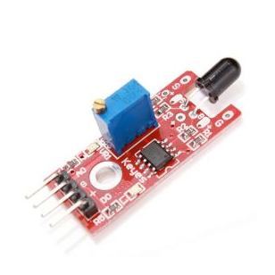
🔌 KY-026 Sensor Pinout
Below you can see the pinout for the KY-026 Flame Sensor Module. The VCC pin is used to supply power to the sensor, and it typically requires 3.3V or 5V (refer to the datasheet for specific voltage requirements). The GND pin is the ground connection and must be connected to the ground of your ESP32!

GND:Connects to ground.+V:Connects to 3.3V or 5V power supply.D0:Digital output; goes high when the detected flame intensity exceeds the set threshold.A0:Analog output; provides a voltage proportional to the detected flame intensity.
🧵 KY-026 Wiring with ESP32
Below you can see the wiring for the KY-026 Flame Sensor Module with the ESP32. Connect the VCC pin of the sensor to the 3.3V pin on the ESP32 or external power supply for power and the GND pin of the sensor to the GND pin of the ESP32. Depending on the communication protocol of the sensor (e.g., I2C, SPI, UART, or analog), connect the appropriate data and clock or signal pins to compatible GPIO pins on the ESP32, as shown below in the wiring diagram.
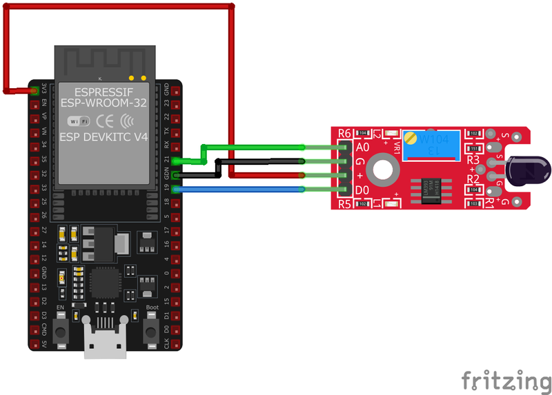
GND:Connect to ESP32GND.+V:Connect to ESP323.3Vor5V.D0:Connect to a digital input pin on ESP32 (e.g.,GPIO17).A0:Connect to an analog input pin on ESP32 (e.g.,GPIO36).
🛠️ KY-026 Flame Sensor Module Troubleshooting
This guide outlines a systematic approach to troubleshoot and resolve common problems with the . Start by confirming that the hardware connections are correct, as wiring mistakes are the most frequent cause of issues. If you are sure the connections are correct, follow the below steps to debug common issues.
❌ No Response from Sensor
Issue: The sensor does not provide any output when exposed to a flame.
Solutions:
- Verify all connections are secure and correctly placed.
- Ensure the module is receiving the appropriate voltage (3.3V or 5V).
- Adjust the potentiometer to set the correct sensitivity threshold.
- Test the sensor with a known flame source to confirm functionality.
⚠️ False Positives
Issue: The sensor triggers without the presence of a flame.
Solutions:
- Reduce the sensitivity by adjusting the potentiometer.
- Avoid exposing the sensor to direct sunlight or other strong light sources.
- Ensure there are no reflective surfaces causing stray light to reach the sensor.
💻 Code Examples
Below you can find code examples of KY-026 Flame Sensor Module with ESP32 in several frameworks:
If you encounter issues while using the KY-026 Flame Sensor Module, check the Common Issues Troubleshooting Guide.

ESP32 KY-026 Arduino IDE Code Example
Fill in your main Arduino IDE sketch file with the following code to use the KY-026 Flame Sensor Module:
// Declaration and initialization of the input pins
int analog_input = A0; // Analog output of the sensor
int digital_input = 3; // Digital output of the sensor

void setup() {
    pinMode(analog_input, INPUT);
    pinMode(digital_input, INPUT);
    Serial.begin(9600); // Serial output with 9600 bps
    Serial.println("KY-026 Flame detection");
}

void loop() {
    float analog_value;
    int digital_value;

    // Current values are read out, converted to the voltage value...
    analog_value = analogRead(analog_input) * (5.0 / 1023.0);
    digital_value = digitalRead(digital_input);

    //... and printed at this point
    Serial.print("Analog voltage value: ");
    Serial.print(analog_value, 4);
    Serial.print(" V, 	 Threshold value: ");

    if (digital_value == 1) {
        Serial.println("reached");
    } else {
        Serial.println("not yet reached");
    }
    Serial.println("----------------------------------------------------------------");
    delay(1000);
}
This Arduino code reads the analog voltage from the KY-026 sensor's analog output and checks the digital output to determine if the flame intensity has surpassed the set threshold. The results are printed to the serial monitor every second.
Connect your ESP32 to your computer via a USB cable, Ensure the correct Board and Port are selected under Tools, Click the "Upload" button in the Arduino IDE to compile and upload the code to your ESP32.

ESP32 KY-026 ESP-IDF Code ExampleExample in Espressif IoT Framework (ESP-IDF)
If you're using ESP-IDF to work with the KY-026 Flame Sensor Module, here's how you can set it up and read data from the sensor. Fill in this code in the main ESP-IDF file:
#include <stdio.h>
#include "freertos/FreeRTOS.h"
#include "freertos/task.h"
#include "driver/adc.h"
#include "driver/gpio.h"

#define FLAME_SENSOR_ANALOG_PIN ADC1_CHANNEL_0 // GPIO36
#define FLAME_SENSOR_DIGITAL_PIN GPIO_NUM_17

void app_main(void) {
    adc1_config_width(ADC_WIDTH_BIT_12);
    adc1_config_channel_atten(FLAME_SENSOR_ANALOG_PIN, ADC_ATTEN_DB_11);
    gpio_set_direction(FLAME_SENSOR_DIGITAL_PIN, GPIO_MODE_INPUT);

    printf("KY-026 Flame Detection\n");
    while (1) {
        int analog_value = adc1_get_raw(FLAME_SENSOR_ANALOG_PIN);
        int digital_value = gpio_get_level(FLAME_SENSOR_DIGITAL_PIN);
        printf("Analog Value: %d, Digital Threshold: %s\n", analog_value, digital_value ? "Flame Detected" : "No Flame");
        vTaskDelay(pdMS_TO_TICKS(1000));
    }
}
This ESP-IDF code reads the analog value from the KY-026 sensor using ADC on GPIO36 and monitors the digital output on GPIO17 to determine if the flame intensity threshold is exceeded. The results are printed every second.
Update the I2C pins (I2C_MASTER_SDA_IO and I2C_MASTER_SCL_IO) to match your ESP32 hardware setup, Use idf.py build to compile the project, Use idf.py flash to upload the code to your ESP32.
ESP32 KY-026 ESPHome Code Example
Fill in this configuration in your ESPHome YAML configuration file (example.yml) to integrate the KY-026 Flame Sensor Module
sensor:
  - platform: adc
    pin: GPIO36
    name: "KY-026 Flame Intensity"
    update_interval: 1s
binary_sensor:
  - platform: gpio
    pin:
      number: GPIO17
      mode: INPUT_PULLUP
    name: "KY-026 Flame Detection"
This ESPHome configuration reads the KY-026 sensor's analog output on GPIO36 and detects the flame threshold trigger using GPIO17 as a binary sensor. Updates are logged every second.
Upload this code to your ESP32 using the ESPHome dashboard or the esphome run command.

ESP32 KY-026 PlatformIO Code Example
For PlatformIO, make sure to configure the platformio.ini file with the appropriate environment and libraries, and then proceed with the code.
Configure platformio.ini
First, your platformio.ini should look like below. You might need to include some libraries as shown. Make sure to change the board to your ESP32:
[env:esp32]
platform = espressif32
board = esp32dev
framework = arduino
ESP32 KY-026 PlatformIO Example Code
Write this code in your PlatformIO project under the src/main.cpp file to use the KY-026 Flame Sensor Module:
#include <Arduino.h>

#define FLAME_SENSOR_ANALOG_PIN A0
#define FLAME_SENSOR_DIGITAL_PIN 17

void setup() {
    pinMode(FLAME_SENSOR_DIGITAL_PIN, INPUT);
    Serial.begin(115200);
    Serial.println("KY-026 Flame Sensor Test");
}

void loop() {
    int analog_value = analogRead(FLAME_SENSOR_ANALOG_PIN);
    int digital_value = digitalRead(FLAME_SENSOR_DIGITAL_PIN);
    Serial.printf("Analog: %d, Digital: %s\n", analog_value, digital_value ? "Flame Detected" : "No Flame");
    delay(1000);
}
This PlatformIO code reads the KY-026 sensor's analog output and monitors the digital flame detection trigger. The values are printed every second.
Upload the code to your ESP32 using the PlatformIO "Upload" button in your IDE or the pio run --target upload command.

ESP32 KY-026 MicroPython Code Example
Fill in this script in your MicroPython main.py file (main.py) to integrate the KY-026 Flame Sensor Module with your ESP32.
import machine
import time

FLAME_SENSOR_ANALOG_PIN = machine.ADC(machine.Pin(36))
FLAME_SENSOR_ANALOG_PIN.atten(machine.ADC.ATTN_11DB)
FLAME_SENSOR_DIGITAL_PIN = machine.Pin(17, machine.Pin.IN, machine.Pin.PULL_UP)

while True:
    analog_value = FLAME_SENSOR_ANALOG_PIN.read()
    digital_value = FLAME_SENSOR_DIGITAL_PIN.value()
    print("Analog:", analog_value, "Digital:", "Flame Detected" if digital_value else "No Flame")
    time.sleep(1)
This MicroPython script reads the KY-026 sensor's analog signal using ADC on GPIO36 and monitors the digital output on GPIO17. The readings are printed every second.
Upload this code to your ESP32 using a MicroPython-compatible IDE, such as Thonny, uPyCraft, or tools like ampy.
Conclusion
We went through technical specifications of KY-026 Flame Sensor Module, its pinout, connection with ESP32 and KY-026 Flame Sensor Module code examples with Arduino IDE, ESP-IDF, ESPHome and PlatformIO.