ESP32 KY-040 Rotary Encoder Module
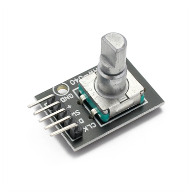
The KY-040 is a rotary encoder module that provides digital signals corresponding to the rotational position and direction. It features continuous 360-degree rotation and includes a built-in push-button switch, making it suitable for various control applications.
⬇️ Jump to Code Examples


🔗 Quick Links

🛒 KY-040 Price


ℹ️ About KY-040 Rotary Encoder Module
The KY-040 Rotary Encoder Module is a rotary input device that provides information about the amount and direction of rotation. Unlike potentiometers, which have limited rotation angles, the KY-040 can rotate continuously, making it ideal for applications requiring precise control, such as volume adjustments, menu navigation, and motor speed control. The module also features a built-in push-button switch, adding an extra layer of functionality.⚙️ KY-040 Sensor Technical Specifications
Below you can see the KY-040 Rotary Encoder Module Technical Specifications. The sensor is compatible with the ESP32, operating within a voltage range suitable for microcontrollers. For precise details about its features, specifications, and usage, refer to the sensor’s datasheet.
- Type: module
- Protocol: Digital
- Operating Voltage: 3.3V to 5V
- Pulses per Revolution: 20
- Output: 2-bit Gray Code
- Mechanical Angle: 360° Continuous
- Built-in Switch: Yes (Push-to-Operate)
- Dimensions: 30mm x 18mm x 30mm
🔌 KY-040 Sensor Pinout
Below you can see the pinout for the KY-040 Rotary Encoder Module. The VCC pin is used to supply power to the sensor, and it typically requires 3.3V or 5V (refer to the datasheet for specific voltage requirements). The GND pin is the ground connection and must be connected to the ground of your ESP32!
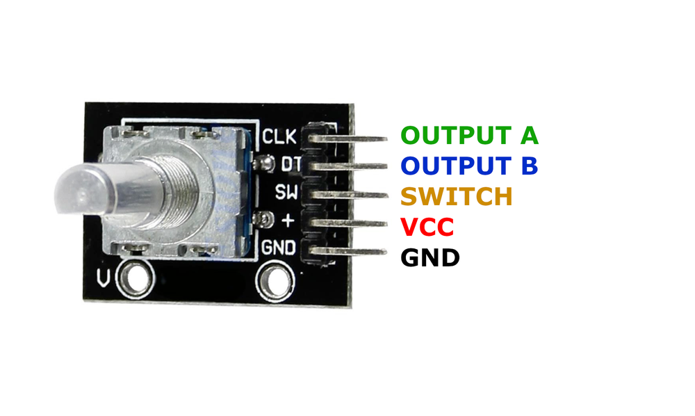
CLK (Clock):Outputs pulses corresponding to the rotation; connect to a digital input pin on the microcontroller.DT (Data):Outputs pulses used in conjunction with CLK to determine rotation direction; connect to a digital input pin on the microcontroller.SW (Switch):Connected to the built-in push-button; connect to a digital input pin on the microcontroller.VCC:Connects to the power supply, typically 3.3V or 5V.GND:Connects to the ground of the circuit.
🛠️ KY-040 Rotary Encoder Module Troubleshooting
This guide outlines a systematic approach to troubleshoot and resolve common problems with the . Start by confirming that the hardware connections are correct, as wiring mistakes are the most frequent cause of issues. If you are sure the connections are correct, follow the below steps to debug common issues.
❌ Unexpected Behavior or No Response
Issue: The module does not respond or behaves erratically when the knob is rotated.
Solutions:
- Ensure all connections are secure and correctly wired according to the pinout diagram.
- Verify that the microcontroller's input pins are properly configured as inputs in the code.
- Check for proper power supply voltage (3.3V or 5V) to the module.
- Implement software debouncing to account for mechanical switch noise.
⚠️ Incorrect Direction Detection
Issue: The detected rotation direction is opposite to the actual rotation.
Solutions:
- Swap the connections of the
CLKandDTpins to correct the direction detection. - Ensure that the code logic correctly interprets the sequence of pulses from the
CLKandDTpins.
💻 Code Examples
Below you can find code examples of KY-040 Rotary Encoder Module with ESP32 in several frameworks:
If you encounter issues while using the KY-040 Rotary Encoder Module, check the Common Issues Troubleshooting Guide.

ESP32 KY-040 Arduino IDE Code Example
Fill in your main Arduino IDE sketch file with the following code to use the KY-040 Rotary Encoder Module:
#define CLK_PIN 3
#define DT_PIN 4
#define SW_PIN 5

int counter = 0;
int currentStateCLK;
int lastStateCLK;
bool currentStateSW;
bool lastStateSW;

void setup() {
    pinMode(CLK_PIN, INPUT);
    pinMode(DT_PIN, INPUT);
    pinMode(SW_PIN, INPUT_PULLUP);
    lastStateCLK = digitalRead(CLK_PIN);
    lastStateSW = digitalRead(SW_PIN);
    Serial.begin(9600);
    Serial.println("KY-040 Rotary Encoder Test");
}

void loop() {
    currentStateCLK = digitalRead(CLK_PIN);
    if (currentStateCLK != lastStateCLK) {
        if (digitalRead(DT_PIN) != currentStateCLK) {
            counter++;
        } else {
            counter--;
        }
        Serial.print("Position: ");
        Serial.println(counter);
    }
    lastStateCLK = currentStateCLK;

    currentStateSW = digitalRead(SW_PIN);
    if (currentStateSW == LOW && lastStateSW == HIGH) {
        Serial.println("Button Pressed");
    }
    lastStateSW = currentStateSW;

    delay(50);
}
This Arduino code sets up the KY-040 rotary encoder using three pins: CLK (Clock), DT (Data), and SW (Switch). It initializes these pins as inputs and continuously monitors the rotation direction and button presses.
When the encoder knob is turned, the CLK and DT pins generate pulses. By comparing the sequence of these pulses, the code determines whether the encoder is rotating clockwise or counterclockwise:
- If the
DTsignal is opposite to theCLKsignal, the counter increments (clockwise rotation). - If the
DTsignal matches theCLKsignal, the counter decrements (counterclockwise rotation).
The position counter is updated accordingly and printed to the serial monitor.
The built-in push-button switch (SW) is also monitored. If pressed, a message is printed to the serial monitor.
A delay(50) is used to debounce the encoder readings, ensuring stable detection of rotation and button presses.
Connect your ESP32 to your computer via a USB cable, Ensure the correct Board and Port are selected under Tools, Click the "Upload" button in the Arduino IDE to compile and upload the code to your ESP32.
ESP32 KY-040 ESP-IDF Code ExampleExample in Espressif IoT Framework (ESP-IDF)
If you're using ESP-IDF to work with the KY-040 Rotary Encoder Module, here's how you can set it up and read data from the sensor. Fill in this code in the main ESP-IDF file:
#include <stdio.h>
#include "freertos/FreeRTOS.h"
#include "freertos/task.h"
#include "driver/gpio.h"

#define CLK_PIN GPIO_NUM_18
#define DT_PIN GPIO_NUM_19
#define SW_PIN GPIO_NUM_21

volatile int counter = 0;
volatile int lastStateCLK;

void IRAM_ATTR encoder_isr_handler(void* arg) {
    int currentStateCLK = gpio_get_level(CLK_PIN);
    if (currentStateCLK != lastStateCLK) {
        if (gpio_get_level(DT_PIN) != currentStateCLK) {
            counter++;
        } else {
            counter--;
        }
        printf("Position: %d\n", counter);
    }
    lastStateCLK = currentStateCLK;
}

void app_main(void) {
    gpio_config_t io_conf = {
        .intr_type = GPIO_INTR_ANYEDGE,
        .mode = GPIO_MODE_INPUT,
        .pin_bit_mask = (1ULL << CLK_PIN) | (1ULL << DT_PIN) | (1ULL << SW_PIN),
        .pull_up_en = GPIO_PULLUP_ENABLE
    };
    gpio_config(&io_conf);

    lastStateCLK = gpio_get_level(CLK_PIN);
    gpio_install_isr_service(0);
    gpio_isr_handler_add(CLK_PIN, encoder_isr_handler, NULL);

    printf("KY-040 Rotary Encoder Test\n");
    while (1) {
        if (gpio_get_level(SW_PIN) == 0) {
            printf("Button Pressed\n");
        }
        vTaskDelay(pdMS_TO_TICKS(100));
    }
}
This ESP-IDF code configures the KY-040 rotary encoder on GPIO18 (CLK), GPIO19 (DT), and GPIO21 (SW). It uses an interrupt service routine (ISR) to detect changes in the encoder's rotation and update a counter. Additionally, it checks for button presses in the main loop and prints the status to the console.
Update the I2C pins (I2C_MASTER_SDA_IO and I2C_MASTER_SCL_IO) to match your ESP32 hardware setup, Use idf.py build to compile the project, Use idf.py flash to upload the code to your ESP32.
ESP32 KY-040 ESPHome Code Example
Fill in this configuration in your ESPHome YAML configuration file (example.yml) to integrate the KY-040 Rotary Encoder Module
sensor:
  - platform: rotary_encoder
    pin_a: GPIO18
    pin_b: GPIO19
    name: "KY-040 Rotary Encoder"
    min_value: -1000
    max_value: 1000
    resolution: 1

binary_sensor:
  - platform: gpio
    pin:
      number: GPIO21
      mode: INPUT_PULLUP
    name: "KY-040 Button"
This ESPHome configuration sets up the KY-040 rotary encoder with GPIO18 and GPIO19 for rotation detection and GPIO21 for the push button. The encoder is configured with a minimum and maximum value range, and its resolution is set to 1 step per increment.
Upload this code to your ESP32 using the ESPHome dashboard or the esphome run command.

ESP32 KY-040 PlatformIO Code Example
For PlatformIO, make sure to configure the platformio.ini file with the appropriate environment and libraries, and then proceed with the code.
Configure platformio.ini
First, your platformio.ini should look like below. You might need to include some libraries as shown. Make sure to change the board to your ESP32:
[env:esp32]
platform = espressif32
board = esp32dev
framework = arduino
ESP32 KY-040 PlatformIO Example Code
Write this code in your PlatformIO project under the src/main.cpp file to use the KY-040 Rotary Encoder Module:
#include <Arduino.h>

#define CLK_PIN 18
#define DT_PIN 19
#define SW_PIN 21

volatile int counter = 0;
int lastStateCLK;

void IRAM_ATTR rotary_encoder() {
    int currentStateCLK = digitalRead(CLK_PIN);
    if (currentStateCLK != lastStateCLK) {
        if (digitalRead(DT_PIN) != currentStateCLK) {
            counter++;
        } else {
            counter--;
        }
        Serial.print("Position: ");
        Serial.println(counter);
    }
    lastStateCLK = currentStateCLK;
}

void setup() {
    pinMode(CLK_PIN, INPUT);
    pinMode(DT_PIN, INPUT);
    pinMode(SW_PIN, INPUT_PULLUP);
    attachInterrupt(digitalPinToInterrupt(CLK_PIN), rotary_encoder, CHANGE);
    Serial.begin(115200);
    Serial.println("KY-040 Rotary Encoder Test");
}

void loop() {
    if (digitalRead(SW_PIN) == LOW) {
        Serial.println("Button Pressed");
        delay(100);
    }
}
This PlatformIO code configures GPIO18 (CLK), GPIO19 (DT), and GPIO21 (SW) for the KY-040 rotary encoder. It uses an interrupt to detect changes in rotation and updates a counter accordingly. The push button state is also monitored and printed to the serial monitor when pressed.
Upload the code to your ESP32 using the PlatformIO "Upload" button in your IDE or the pio run --target upload command.
ESP32 KY-040 MicroPython Code Example
Fill in this script in your MicroPython main.py file (main.py) to integrate the KY-040 Rotary Encoder Module with your ESP32.
import machine
import time

CLK_PIN = machine.Pin(18, machine.Pin.IN, machine.Pin.PULL_UP)
DT_PIN = machine.Pin(19, machine.Pin.IN, machine.Pin.PULL_UP)
SW_PIN = machine.Pin(21, machine.Pin.IN, machine.Pin.PULL_UP)

counter = 0
last_state_clk = CLK_PIN.value()

while True:
    current_state_clk = CLK_PIN.value()
    if current_state_clk != last_state_clk:
        if DT_PIN.value() != current_state_clk:
            counter += 1
        else:
            counter -= 1
        print("Position:", counter)
    last_state_clk = current_state_clk

    if SW_PIN.value() == 0:
        print("Button Pressed")
        time.sleep(0.1)
    time.sleep(0.05)
This MicroPython script configures GPIO18 (CLK), GPIO19 (DT), and GPIO21 (SW) for the KY-040 rotary encoder. It continuously monitors the encoder rotation and updates a counter while also detecting button presses.
Upload this code to your ESP32 using a MicroPython-compatible IDE, such as Thonny, uPyCraft, or tools like ampy.
Conclusion
We went through technical specifications of KY-040 Rotary Encoder Module, its pinout, connection with ESP32 and KY-040 Rotary Encoder Module code examples with Arduino IDE, ESP-IDF, ESPHome and PlatformIO.