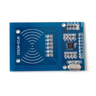
ESP32 RC522 RFID/NFC Module
The RC522 RFID/NFC module offers an affordable and reliable solution for integrating NFC and RFID functionality into your projects. Its compact size, multi-protocol support, and robust performance make it a great choice for a wide range of applications.
Jump to Code Examples
Quick Links
RC522 Price
About RC522 RFID/NFC Module
The RC522 is a cost-effective and compact RFID/NFC module ideal for proximity identification and security applications. Supporting both SPI, I2C, and UART communication protocols, the RC522 is easy to integrate into microcontroller-based projects. It is compatible with ISO/IEC 14443 Type A cards and tags, making it perfect for access control, payment systems, and similar NFC-based applications.RC522 Sensor Technical Specifications
Below you can see the RC522 RFID/NFC Module Technical Specifications. The sensor is compatible with the ESP32, operating within a voltage range suitable for microcontrollers. For precise details about its features, specifications, and usage, refer to the sensor’s datasheet.
- Protocol: SPI/I2C/UART
- Communication Protocols: SPI, I2C, UART
- Operating Voltage: 3.3V
- Supported Standards: ISO/IEC 14443 Type A
- Operating Temperature: -20°C to +80°C
- Dimensions: 40mm x 60mm x 3mm
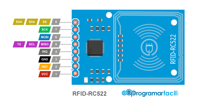
RC522 Sensor Pinout
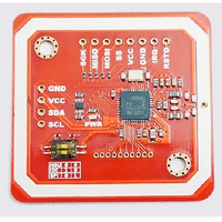
Below you can see the pinout for the RC522 RFID/NFC Module. The VCC pin is used to supply power to the sensor, and it typically requires 3.3V or 5V (refer to the datasheet for specific voltage requirements). The GND pin is the ground connection and must be connected to the ground of your ESP32!
The RC522 pinout includes:
- VCC: Power supply input (3.3V).
- GND: Ground connection.
- RST: Reset signal input (active low).
- IRQ: Interrupt signal output.
- MISO: SPI Master In Slave Out.
- MOSI: SPI Master Out Slave In.
- SCK: SPI clock line.
- SDA: I2C data line or SPI slave select.
RC522 Wiring with ESP32
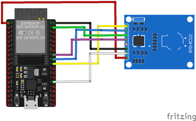
Below you can see the wiring for the RC522 RFID/NFC Module with the ESP32. Connect the VCC pin of the sensor to the 3.3V pin on the ESP32 or external power supply for power and the GND pin of the sensor to the GND pin of the ESP32. Depending on the communication protocol of the sensor (e.g., I2C, SPI, UART, or analog), connect the appropriate data and clock or signal pins to compatible GPIO pins on the ESP32, as shown below in the wiring diagram.
- Connect
VCCto a stable 3.3V power supply. - Connect
GNDto the system ground. - For SPI: Connect
MISO,MOSI,SCK, andSDAto the respective SPI pins on the microcontroller. UseRSTfor reset control. - For I2C: Connect
SDAto the microcontroller's SDA pin andSCKto the SCL pin. - For UART: Use appropriate UART lines (if available on the module version).
Code Examples
Below you can find code examples of RC522 RFID/NFC Module with ESP32 in several frameworks:
If you encounter issues while using the RC522 RFID/NFC Module, check the Common Issues Troubleshooting Guide.

ESP32 RC522 Arduino IDE Code Example
Fill in your main Arduino IDE sketch file with the following code to use the RC522 RFID/NFC Module:
#include <SPI.h>
#include <MFRC522.h>

#define RST_PIN 9
#define SS_PIN 10
MFRC522 rfid(SS_PIN, RST_PIN);

void setup() {
    Serial.begin(115200);
    SPI.begin();
    rfid.PCD_Init();
    Serial.println("RC522 initialized. Waiting for cards...");
}

void loop() {
    if (!rfid.PICC_IsNewCardPresent() || !rfid.PICC_ReadCardSerial()) {
        delay(50);
        return;
    }

    Serial.print("Card UID: ");
    for (byte i = 0; i < rfid.uid.size; i++) {
        Serial.print(rfid.uid.uidByte[i], HEX);
        Serial.print(" ");
    }
    Serial.println();

    rfid.PICC_HaltA();
}
This Arduino sketch interfaces with the RC522 module over SPI using the MFRC522 library. The `setup` function initializes the module, while the `loop` scans for RFID cards and prints their UIDs when detected. Additional functionality, such as reading or writing card data, can be implemented using the MFRC522 library.
Connect your ESP32 to your computer via a USB cable, Ensure the correct Board and Port are selected under Tools, Click the "Upload" button in the Arduino IDE to compile and upload the code to your ESP32.
ESP32 RC522 ESP-IDF Code ExampleExample in Espressif IoT Framework (ESP-IDF)
If you're using ESP-IDF to work with the RC522 RFID/NFC Module, here's how you can set it up and read data from the sensor. Fill in this code in the main ESP-IDF file:
#include <stdio.h>
#include "driver/spi_master.h"
#include "driver/gpio.h"
#include "freertos/task.h"
#include "rc522.h"

#define RST_PIN GPIO_NUM_21
#define SS_PIN GPIO_NUM_22
#define MISO_PIN GPIO_NUM_19
#define MOSI_PIN GPIO_NUM_23
#define SCK_PIN GPIO_NUM_18

void app_main() {
    printf("Initializing RC522...");
    rc522_config_t config = {
        .spi_miso_io = MISO_PIN,
        .spi_mosi_io = MOSI_PIN,
        .spi_sck_io = SCK_PIN,
        .spi_cs_io = SS_PIN,
        .reset_io = RST_PIN
    };

    rc522_handle_t handle = rc522_create(&config);
    if (handle == NULL) {
        printf("Failed to initialize RC522\n");
        return;
    }

    while (true) {
        rc522_tag_t tag;
        if (rc522_read_tag(handle, &tag) == ESP_OK) {
            printf("Tag UID: ");
            for (int i = 0; i < tag.uid_size; i++) {
                printf("%02X ", tag.uid[i]);
            }
            printf("\n");
        }
        vTaskDelay(pdMS_TO_TICKS(500));
    }
}
This ESP-IDF code initializes the RC522 RFID module over SPI. The module continuously scans for RFID tags and logs their UIDs. The `rc522_read_tag` function retrieves tag information when available. Additional functionalities like writing to cards can be implemented using the RC522 driver.
Update the I2C pins (I2C_MASTER_SDA_IO and I2C_MASTER_SCL_IO) to match your ESP32 hardware setup, Use idf.py build to compile the project, Use idf.py flash to upload the code to your ESP32.

ESP32 RC522 ESPHome Code Example
Fill in this configuration in your ESPHome YAML configuration file (example.yml) to integrate the RC522 RFID/NFC Module
spi:
  clk_pin: GPIO18
  mosi_pin: GPIO23
  miso_pin: GPIO19

rc522:
  cs_pin: GPIO22
  rst_pin: GPIO21
  update_interval: 2s

sensor:
  - platform: rc522
    uid:
      name: "RFID Tag UID"
    log:
      name: "RFID Log"
This ESPHome configuration sets up the RC522 RFID module over SPI. The module is updated every 2 seconds to scan for RFID tags. Detected tag UIDs are logged and available as a sensor output. The configuration can be extended for writing to tags or using the tag data in automations.
Upload this code to your ESP32 using the ESPHome dashboard or the esphome run command.

ESP32 RC522 PlatformIO Code Example
For PlatformIO, make sure to configure the platformio.ini file with the appropriate environment and libraries, and then proceed with the code.
Configure platformio.ini
First, your platformio.ini should look like below. You might need to include some libraries as shown. Make sure to change the board to your ESP32:
[env:rc522]
platform = espressif32
board = esp32dev
framework = arduino
monitor_speed = 115200
ESP32 RC522 PlatformIO Example Code
Write this code in your PlatformIO project under the src/main.cpp file to use the RC522 RFID/NFC Module:
#include <SPI.h>
#include <MFRC522.h>

#define RST_PIN 21
#define SS_PIN 22
MFRC522 rfid(SS_PIN, RST_PIN);

void setup() {
    Serial.begin(115200);
    SPI.begin();
    rfid.PCD_Init();
    Serial.println("RC522 initialized. Waiting for cards...");
}

void loop() {
    if (!rfid.PICC_IsNewCardPresent() || !rfid.PICC_ReadCardSerial()) {
        delay(50);
        return;
    }

    Serial.print("Card UID: ");
    for (byte i = 0; i < rfid.uid.size; i++) {
        Serial.print(rfid.uid.uidByte[i], HEX);
        Serial.print(" ");
    }
    Serial.println();

    rfid.PICC_HaltA();
}
This PlatformIO example interfaces with the RC522 module using the MFRC522 library over SPI. The code initializes the module, scans for RFID tags, and logs their UIDs to the Serial Monitor. Additional NFC features can be implemented using the library.
Upload the code to your ESP32 using the PlatformIO "Upload" button in your IDE or the pio run --target upload command.
ESP32 RC522 MicroPython Code Example
Fill in this script in your MicroPython main.py file (main.py) to integrate the RC522 RFID/NFC Module with your ESP32.
from machine import Pin, SPI
from mfrc522 import MFRC522
import time

spi = SPI(1, baudrate=1000000, sck=Pin(18), mosi=Pin(23), miso=Pin(19))
rst = Pin(21, Pin.OUT)
cs = Pin(22, Pin.OUT)

reader = MFRC522(spi, cs, rst)

while True:
    print("Waiting for card...")
    (status, tag_type) = reader.request(reader.REQIDL)

    if status == reader.OK:
        (status, uid) = reader.anticoll()
        if status == reader.OK:
            print("Card UID:", [hex(i) for i in uid])
    time.sleep(1)
This MicroPython example uses the MFRC522 library to interface with the RC522 module over SPI. It continuously scans for RFID tags, and when detected, prints their UIDs. Additional functionalities, such as reading or writing data to cards, can be added using the library.
Upload this code to your ESP32 using a MicroPython-compatible IDE, such as Thonny, uPyCraft, or tools like ampy.
RC522 RFID/NFC Module Troubleshooting
This guide outlines a systematic approach to troubleshoot and resolve common problems with the . Start by confirming that the hardware connections are correct, as wiring mistakes are the most frequent cause of issues. If you are sure the connections are correct, follow the below steps to debug common issues.
Module Fails to Power On
Issue: The RC522 module does not power up or respond to commands.
Possible causes include insufficient power supply, incorrect wiring, or faulty hardware.
Solution: Ensure the module is connected to a stable power source within the recommended voltage range of 3.3V to 5V. Verify that all connections are secure and correctly configured. If the problem persists, consider testing the module with a different power source or replacing it.
Communication Interface Not Working
Issue: The module fails to communicate with the microcontroller over the chosen interface (SPI).
Possible causes include incorrect wiring, improper interface selection, or incompatible voltage levels.
Solution: Double-check the wiring to ensure correct connections for SPI communication. For SPI, verify the MOSI, MISO, SCK, and SS lines are properly connected. Ensure that the microcontroller's SPI interface is enabled and configured correctly.
Unable to Read Tags
Issue: The module initializes correctly but fails to read RFID tags.
Possible causes include incorrect antenna orientation, insufficient power supply, or interference from nearby electronic devices.
Solution: Ensure the module's antenna is properly oriented and positioned near the tags. Verify that the power supply provides adequate current for the module's operation. Keep the module away from sources of electromagnetic interference.
Inconsistent Tag Detection
Issue: The module detects tags intermittently or with delays.
Possible causes include low-quality tags, environmental interference, or firmware issues.
Solution: Test with different tags to rule out tag quality issues. Ensure the operating environment is free from strong electromagnetic interference. Update the module's firmware to the latest version to benefit from bug fixes and improvements.
Library or Software Issues
Issue: The module operates erratically or produces errors during operation.
Possible causes include outdated or incompatible libraries, incorrect initialization, or software bugs.
Solution: Ensure that the latest version of the MFRC522 library is installed and compatible with your development environment. Review the initialization code to confirm that the module is set up correctly. Consult the module's documentation and community forums for guidance on proper usage.
Conclusion
We went through technical specifications of RC522 RFID/NFC Module, its pinout, connection with ESP32 and RC522 RFID/NFC Module code examples with Arduino IDE, ESP-IDF, ESPHome and PlatformIO.

