ESP32 SIM800L GSM/GPRS Module
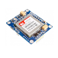
The SIM800L is a GSM/GPRS communication module that supports voice, SMS, and data transmission. It is ideal for IoT applications requiring wireless connectivity over quad-band GSM networks.
⬇️ Jump to Code Examples


🔗 Quick Links


🛒 SIM800L Price


ℹ️ About SIM800L GSM/GPRS Module
The SIM800L is a quad-band GSM/GPRS module (850/900/1800/1900MHz) designed for SMS, voice, and data communication in IoT and embedded systems.
⚡ Key Features #
- Quad-Band GSM Connectivity – Works worldwide on 850/900/1800/1900MHz networks.
- Compact & Low Power – Ideal for battery-powered IoT applications.
- Versatile Communication – Supports SMS, voice calls, and GPRS data transfer.
- Internet-Ready – Built-in TCP/IP, HTTP, FTP, and MMS support for online communication.
🔗 Still choosing a SIM module? Check the ESP32 SIM Modules Comparison Table for a detailed breakdown of LTE, 3G, and GPRS options.
⚙️ SIM800L Sensor Technical Specifications
Below you can see the SIM800L GSM/GPRS Module Technical Specifications. The sensor is compatible with the ESP32, operating within a voltage range suitable for microcontrollers. For precise details about its features, specifications, and usage, refer to the sensor’s datasheet.
- Type: sim
- Protocol: UART
- Frequency Bands: Quad-band 850/900/1800/1900MHz
- Voltage Range: 3.4V to 4.4V
- Current Consumption (Sleep Mode): 0.7mA
- Dimensions: 15.8mm x 17.8mm x 2.4mm
- Temperature Range: -40°C to +85°C
- Protocol Support: TCP/IP, HTTP, FTP, MMS
- SIM Card: Supports 1.8V and 3V SIM cards
- Interface: UART (AT Command)
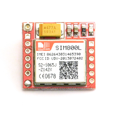
🔌 SIM800L Sensor Pinout
Below you can see the pinout for the SIM800L GSM/GPRS Module. The VCC pin is used to supply power to the sensor, and it typically requires 3.3V or 5V (refer to the datasheet for specific voltage requirements). The GND pin is the ground connection and must be connected to the ground of your ESP32!

The SIM800L pinout includes:
- VCC: Power input (3.4V to 4.4V).
- GND: Ground connection.
- RXD: UART Receive pin (connects to microcontroller TX).
- TXD: UART Transmit pin (connects to microcontroller RX).
- RST: Reset pin (active low).
- NET: External antenna pad for better signal reception.
🧵 SIM800L Wiring with ESP32
Below you can see the wiring for the SIM800L GSM/GPRS Module with the ESP32. Connect the VCC pin of the sensor to the 3.3V pin on the ESP32 or external power supply for power and the GND pin of the sensor to the GND pin of the ESP32. Depending on the communication protocol of the sensor (e.g., I2C, SPI, UART, or analog), connect the appropriate data and clock or signal pins to compatible GPIO pins on the ESP32, as shown below in the wiring diagram.
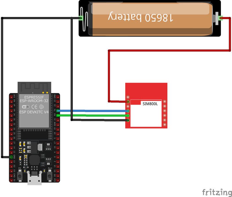
- Connect
VCCto a stable 4V power source. - Connect
GNDto the ground of the microcontroller. - Attach
TXDto the RX pin of the microcontroller andRXDto the TX pin. - Optionally, connect
RSTto a GPIO pin for resetting the module. - Ensure a proper external antenna is connected to the
NETpin for better signal reception.
🛠️ SIM800L GSM/GPRS Module Troubleshooting
This guide outlines a systematic approach to troubleshoot and resolve common problems with the . Start by confirming that the hardware connections are correct, as wiring mistakes are the most frequent cause of issues. If you are sure the connections are correct, follow the below steps to debug common issues.
🔄 Module Continuously Resets or Reboots
Issue: The SIM800L module restarts frequently, indicated by the status LED turning off and on repeatedly.
Possible causes include insufficient power supply or voltage drops due to wiring.
Solution: Use a dedicated power supply capable of providing 4V and at least 2A. Incorporate low ESR capacitors (e.g., 100µF tantalum and 470µF electrolytic) close to the module's power pins to handle current spikes. Additionally, use short, thick wires (e.g., 22AWG) to minimize resistance and ensure consistent voltage levels.
📶 Failure to Connect to the Cellular Network
Issue: The module's network LED blinks rapidly, indicating it is not registered on the network.
Possible causes include incorrect SIM card configuration, poor signal strength, or frequency mismatch.
Solution: Ensure the SIM card is active, has sufficient balance, and the PIN lock is disabled. Check the external antenna connection and position it in a location with better network coverage. Verify that the module supports the cellular network's frequency bands in your region.
🔧 UART Communication Issues
Issue: No response from the module when sending AT commands.
Possible causes include incorrect baud rate, wiring errors, or power instability.
Solution: Ensure that the module and the microcontroller are set to the same baud rate (default is 9600). Confirm the RX and TX pins are connected correctly (RX to TX and TX to RX). Use a stable power source and add decoupling capacitors to avoid power fluctuations.
📡 Unstable GSM Signal
Issue: The SIM800L fails to maintain a stable connection, resulting in dropped calls or intermittent data transmission.
Possible causes include poor antenna placement or interference from nearby electronics.
Solution: Use a proper external antenna and position it away from other electronic components that may cause interference. Ensure that the antenna connection to the NET pin is secure.
💻 Code Examples
Below you can find code examples of SIM800L GSM/GPRS Module with ESP32 in several frameworks:
If you encounter issues while using the SIM800L GSM/GPRS Module, check the Common Issues Troubleshooting Guide.

ESP32 SIM800L Arduino IDE Code Example
Fill in your main Arduino IDE sketch file with the following code to use the SIM800L GSM/GPRS Module:
#include <Arduino.h>

// Define baud rate for Serial communication
#define SERIAL_BAUD 115200
#define SIM800_BAUD 9600  // SIM800L default baud rate

// Initialize Serial2 (UART2) on ESP32 (RX=16, TX=17)
HardwareSerial serial2(2);

void setup() {
  // Initialize Serial Monitor
  Serial.begin(SERIAL_BAUD);
  delay(1000);  // Small delay to stabilize serial

  // Initialize SIM800L Serial (Serial2)
  serial2.begin(SIM800_BAUD, SERIAL_8N1, 16, 17); // TX=17, RX=16
  delay(1000);

  Serial.println("
SIM800 EVB to ESP32 Serial port 2 test");
  Serial.println("Sending AT commands to check communication...
");

  // Send AT command and check response
  sendATCommand("AT");          // Check if module is responding
  sendATCommand("AT+CGMI");     // Get manufacturer name
  sendATCommand("AT+CGMM");     // Get module model number
  sendATCommand("AT+CGMR");     // Get firmware version
  sendATCommand("AT+CGSN");     // Get serial number
}

void loop() {
  // Read data from SIM800L and print to Serial Monitor
  while (serial2.available() > 0) {
    Serial.write(serial2.read());
  }

  // Read data from Serial Monitor and send to SIM800L
  while (Serial.available() > 0) {
    serial2.write(Serial.read());
  }
}

// Function to send AT command and wait for response
void sendATCommand(const char *command) {
  Serial.print("Sending: ");
  Serial.println(command);
  serial2.println(command);  // Send command to SIM800L
  delay(1000);               // Wait for response

  // Print response from SIM800L
  while (serial2.available()) {
    Serial.write(serial2.read());
  }
  Serial.println("----------------------");
}
This Arduino sketch interfaces with the SIM800L module using the ESP32's hardware serial communication (UART2). The ESP32 has multiple hardware serial ports, and this code uses Serial2 for communication with the SIM800L module.
Hardware Serial (UART2) #
Unlike SoftwareSerial, which is used on boards like Arduino Uno, ESP32 has dedicated hardware UARTs. This code initializes Serial2 with the correct baud rate and assigns GPIO pins for RX and TX:
serial2.begin(9600, SERIAL_8N1, 16, 17);- Pin 16 (RX) and Pin 17 (TX) are used for UART communication.
- The baud rate for SIM800L is set to
9600.
Setup Process #
Serial.begin(115200);initializes the Serial Monitor for debugging.serial2.begin()initializes communication with SIM800L over hardware serial.- The sketch sends a series of AT commands (
AT,AT+CGMI,AT+CGMM,AT+CGMR,AT+CGSN) to check the module’s response.
Loop Function #
- Any data received from the SIM800L module is read and printed to the Serial Monitor.
- Any input from the Serial Monitor is forwarded to the SIM800L module.
Sending AT Commands #
A function sendATCommand() is used to send commands and wait for responses:
- It prints the command to the Serial Monitor.
- Sends the command to the SIM800L module.
- Waits for a response and prints it.
This sketch allows real-time communication with the SIM800L module through Serial Monitor, making it useful for debugging and testing AT commands.
Connect your ESP32 to your computer via a USB cable, Ensure the correct Board and Port are selected under Tools, Click the "Upload" button in the Arduino IDE to compile and upload the code to your ESP32.

ESP32 SIM800L ESP-IDF Code ExampleExample in Espressif IoT Framework (ESP-IDF)
If you're using ESP-IDF to work with the SIM800L GSM/GPRS Module, here's how you can set it up and read data from the sensor. Fill in this code in the main ESP-IDF file:
#include <stdio.h>
#include <string.h>
#include "driver/uart.h"
#include "freertos/task.h"

#define TX_PIN 17
#define RX_PIN 16
#define UART_PORT UART_NUM_1

void app_main(void) {
    uart_config_t uart_config = {
        .baud_rate = 9600,
        .data_bits = UART_DATA_8_BITS,
        .parity = UART_PARITY_DISABLE,
        .stop_bits = UART_STOP_BITS_1,
        .flow_ctrl = UART_HW_FLOWCTRL_DISABLE
    };

    uart_param_config(UART_PORT, &uart_config);
    uart_set_pin(UART_PORT, TX_PIN, RX_PIN, UART_PIN_NO_CHANGE, UART_PIN_NO_CHANGE);
    uart_driver_install(UART_PORT, 1024, 0, 0, NULL, 0);

    char *test_cmd = "AT\r\n";
    uart_write_bytes(UART_PORT, test_cmd, strlen(test_cmd));

    while (true) {
        char data[128];
        int len = uart_read_bytes(UART_PORT, data, sizeof(data), 100 / portTICK_PERIOD_MS);
        if (len > 0) {
            data[len] = '\0';
            printf("Response: %s\n", data);
        }
        vTaskDelay(1000 / portTICK_PERIOD_MS);
    }
}
This ESP-IDF example demonstrates UART communication with the SIM800L module. The UART interface is configured with GPIO17 as TX and GPIO16 as RX. An AT command is sent to test communication, and responses from the module are printed to the console. The module’s replies are read using the uart_read_bytes function in a loop.
Update the I2C pins (I2C_MASTER_SDA_IO and I2C_MASTER_SCL_IO) to match your ESP32 hardware setup, Use idf.py build to compile the project, Use idf.py flash to upload the code to your ESP32.

ESP32 SIM800L ESPHome Code Example
Fill in this configuration in your ESPHome YAML configuration file (example.yml) to integrate the SIM800L GSM/GPRS Module
uart:
  baud_rate: 9600
  tx_pin: TX
  rx_pin: RX

sim800l:
  on_sms_received:
    - logger.log:
        format: "Received '%s' from %s"
        args: [ 'message.c_str()', 'sender.c_str()' ]

logger:
  baud_rate: 0 # disable uart logger on esp 8266
This ESPHome configuration sets up UART communication with the SIM800L module at a baud rate of 9600. The SIM800L integration allows receiving SMS messages and logging them.
The UART component is used to communicate with the SIM800L module. The tx_pin and rx_pin should be set according to the GPIO pins connected to the module, and the baud rate is set to 9600 to match the default communication speed of the SIM800L.
The SIM800L integration includes an event that triggers whenever an SMS is received. The message content and sender number are logged using the ESPHome logger component.
The logger component is configured with baud_rate: 0 to disable UART logging, which is necessary when using ESP8266, as it only has one hardware UART.
For more details on integrating SIM800L with ESPHome, refer to the official documentation:
🔗 ESPHome SIM800L Integration
Upload this code to your ESP32 using the ESPHome dashboard or the esphome run command.

ESP32 SIM800L PlatformIO Code Example
For PlatformIO, make sure to configure the platformio.ini file with the appropriate environment and libraries, and then proceed with the code.
Configure platformio.ini
First, your platformio.ini should look like below. You might need to include some libraries as shown. Make sure to change the board to your ESP32:
[env:sim800l]
platform = espressif32
board = esp32dev
framework = arduino
monitor_speed = 115200
ESP32 SIM800L PlatformIO Example Code
Write this code in your PlatformIO project under the src/main.cpp file to use the SIM800L GSM/GPRS Module:
#include <HardwareSerial.h>

HardwareSerial sim800l(1);

void setup() {
    Serial.begin(115200);
    sim800l.begin(9600, SERIAL_8N1, 16, 17); // RX, TX

    sim800l.println("AT"); // Test AT command
    delay(1000);
    while (sim800l.available()) {
        Serial.write(sim800l.read());
    }
}

void loop() {
    sim800l.println("AT+CMGF=1"); // Set SMS to text mode
    delay(1000);
    sim800l.println("AT+CMGS=\"+1234567890\""); // Replace with recipient's number
    delay(1000);
    sim800l.print("Hello from PlatformIO");
    delay(1000);
    sim800l.write(26); // CTRL+Z to send SMS
    delay(5000);
}
This PlatformIO code interfaces with the SIM800L module using HardwareSerial on an ESP32. The AT command is sent to test communication, and SMS functionality is implemented in the loop. GPIO16 (RX) and GPIO17 (TX) are configured as serial pins.
Upload the code to your ESP32 using the PlatformIO "Upload" button in your IDE or the pio run --target upload command.

ESP32 SIM800L MicroPython Code Example
Fill in this script in your MicroPython main.py file (main.py) to integrate the SIM800L GSM/GPRS Module with your ESP32.
from machine import UART
import time

# Initialize UART
uart = UART(2, baudrate=9600, tx=17, rx=16)

def send_at(command):
    uart.write(command + '\r\n')
    time.sleep(1)
    while uart.any():
        print(uart.read().decode('utf-8'), end='')

# Test communication
send_at('AT')

# Send SMS
send_at('AT+CMGF=1')  # Set SMS to text mode
send_at('AT+CMGS="+1234567890"')  # Replace with recipient's number
uart.write("Hello from MicroPython" + chr(26))
This MicroPython code communicates with the SIM800L module over UART. It defines a function to send AT commands and display the response. The script tests communication with an AT command and sends an SMS by setting the module to SMS text mode, specifying the recipient, and finalizing the message with CTRL+Z (ASCII 26).
Upload this code to your ESP32 using a MicroPython-compatible IDE, such as Thonny, uPyCraft, or tools like ampy.
Conclusion
We went through technical specifications of SIM800L GSM/GPRS Module, its pinout, connection with ESP32 and SIM800L GSM/GPRS Module code examples with Arduino IDE, ESP-IDF, ESPHome and PlatformIO.