ESP32 CCS811 Digital Gas Sensor Pinout, Wiring, ESP32 and more
Overview
The CCS811 is a digital gas sensor for monitoring indoor air quality. It measures levels of Total Volatile Organic Compounds (TVOCs) and equivalent CO₂ (eCO₂), providing valuable data for applications like air purifiers, HVAC systems, and smart home devices. Operating over an I²C interface, it simplifies integration into various projects.
About CCS811 Digital Gas Sensor
The CCS811 is an ultra-low power digital gas sensor designed for indoor air quality monitoring. It detects volatile organic compounds (VOCs) and provides equivalent CO₂ (eCO₂) levels, making it useful for smart home automation, HVAC systems, and environmental monitoring.
⚡ Key Features
- VOC & eCO₂ Detection – Monitors air quality and pollution levels.
- Integrated MCU & ADC – Simplifies processing and reduces external component requirements.
- Ultra-Low Power Consumption – Ideal for battery-powered applications.
- I²C Interface – Seamlessly integrates with ESP32, Arduino, and other microcontrollers.
Where to Buy CCS811 Digital Gas Sensor


Prices are subject to change. We earn from qualifying purchases as an Amazon Associate.
CCS811 Datasheet and Technical Specifications
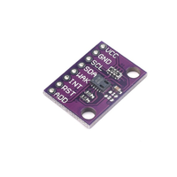
CCS811 Pinout Diagram
The VCC pin is used to supply power to the sensor, and it typically requires 3.3V or 5V (refer to the datasheet for specific voltage requirements). The GND pin is the ground connection and must be connected to the ground of your ESP32.
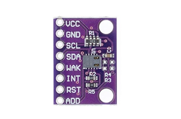
The CCS811 pinout is as follows:
- VDD: Supply voltage (3.3V to 5V).
- GND: Ground connection.
- SDA: I²C data line.
- SCL: I²C clock line.
- nWAKE: Wake pin (active low; connect to GND to enable communication).
- nINT: Interrupt pin (optional; indicates data ready).
- nRESET: Reset pin (active low; optional).
- ADDR: I²C address select (connect to GND for 0x5A or VDD for 0x5B).
CCS811 Wiring with ESP32
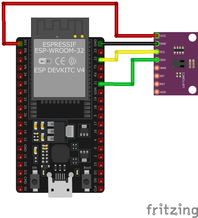
VDD to a 3.3V or 5V power source, GND to ground, SDA to the microcontroller's SDA pin, and SCL to the microcontroller's SCL pin. Connect nWAKE to GND to enable communication. The I²C address can be set by connecting ADDR to GND (0x5A) or VDD (0x5B). Ensure that the I²C communication parameters are correctly configured in your code.CCS811 Troubleshooting Guide
Common Issues
🔄 Intermittent Sensor Hang-ups on ESP8266
Issue: The CCS811 sensor intermittently hangs when connected to an ESP8266, resulting in failed read attempts and the error: False (255).
Possible causes include the ESP8266's inability to handle the CCS811's clock stretching requirements, leading to communication failures.
Solution: Implement clock stretching support by adjusting the I2C communication settings. Adding a delay in the I2C operations can help accommodate the sensor's timing requirements. Additionally, ensure that the sensor's firmware is up to date and consider using a microcontroller with better I2C clock stretching support if the issue persists. (forums.adafruit.com)
❌ Initialization Failure on ESP8266
Issue: The CCS811 sensor fails to initialize on an ESP8266, displaying errors such as: setup: CCS811 begin FAILED and CCS811: I2C error.
Possible causes include incorrect wiring, lack of pull-up resistors on the I2C lines, or the ESP8266's inadequate handling of I2C clock stretching.
Solution: Verify that SDA and SCL are correctly connected to the ESP8266's designated pins and that appropriate pull-up resistors (typically 4.7kΩ) are present on the I2C lines. Since the ESP8266 may not handle I2C clock stretching well, consider adding delays in the I2C communication or using a library that accounts for this limitation. Additionally, ensure that the sensor's WAKE pin is properly managed, either by connecting it to ground or controlling it via a GPIO pin. (forum.arduino.cc)
⚠️ Remote I/O Error on ESP32
Issue: When interfacing the CCS811 sensor with a ESP32, the following error occurs: OSError: [Errno 121] Remote I/O error.
Possible causes include incorrect I2C address configuration, insufficient handling of clock stretching, or wiring issues.
Solution: Confirm the sensor's I2C address using i2cdetect and ensure your code references the correct address (commonly 0x5A or 0x5B). The Raspberry Pi may struggle with the CCS811's clock stretching; therefore, reduce the I2C bus speed by adding dtparam=i2c_arm_baudrate=10000 to /boot/config.txt and rebooting. Verify that the sensor's connections are secure and that the Raspberry Pi's I2C interface is enabled and functioning correctly. (forum.sparkfun.com)
❓ Reading Error Code 2 on Particle Devices
Issue: When reading data from the CCS811 sensor on Particle devices, the sensor returns an error code: ERROR! 2.
Possible causes include insufficient warm-up time for the sensor or issues with the initialization sequence.
Solution: Allow the sensor adequate warm-up time before attempting to read data, as the CCS811 requires a stabilization period after power-up. Ensure that your initialization code follows the recommended sequence as per the sensor's datasheet. If the problem persists, consider using an alternative library that may better handle the sensor's initialization and data retrieval processes. (community.particle.io)
Debugging Tips
🔍 Serial Monitor
Use the Serial Monitor to check for error messages and verify the sensor's output. Add debug prints in your code to track the sensor's state.
⚡ Voltage Checks
Use a multimeter to verify voltage levels and check for continuity in your connections. Ensure the power supply is stable and within the sensor's requirements.
Additional Resources
CCS811 Code Examples
Arduino Example
#include <Wire.h>
#include "Adafruit_CCS811.h"

Adafruit_CCS811 ccs;

void setup() {
    Serial.begin(9600);
    Wire.begin();
    if (!ccs.begin()) {
        Serial.println("Failed to start sensor! Please check your wiring.");
        while (1);
    }
    // Wait for the sensor to be ready
    while (!ccs.available());
}

void loop() {
    if (ccs.available()) {
        if (!ccs.readData()) {
            Serial.print("eCO2: ");
            Serial.print(ccs.geteCO2());
            Serial.print(" ppm, TVOC: ");
            Serial.print(ccs.getTVOC());
            Serial.println(" ppb");
        } else {
            Serial.println("Error reading sensor data");
        }
    }
    delay(1000);
}setup() function, the sensor is initialized, and the code waits until the sensor is ready. The loop() function checks if new data is available and reads the eCO₂ and TVOC levels, printing them to the Serial Monitor every second.ESP-IDF Example
#include <stdio.h>
#include "driver/i2c.h"
#include "ccs811.h"

#define I2C_MASTER_SCL_IO 22
#define I2C_MASTER_SDA_IO 21
#define I2C_MASTER_NUM I2C_NUM_0
#define I2C_MASTER_FREQ_HZ 100000

void app_main(void) {
    i2c_config_t i2c_config = {
        .mode = I2C_MODE_MASTER,
        .sda_io_num = I2C_MASTER_SDA_IO,
        .scl_io_num = I2C_MASTER_SCL_IO,
        .sda_pullup_en = GPIO_PULLUP_ENABLE,
        .scl_pullup_en = GPIO_PULLUP_ENABLE,
        .master.clk_speed = I2C_MASTER_FREQ_HZ
    };
    i2c_param_config(I2C_MASTER_NUM, &i2c_config);
    i2c_driver_install(I2C_MASTER_NUM, I2C_MODE_MASTER, 0, 0, 0);

    ccs811_t sensor;
    ccs811_init(&sensor, I2C_MASTER_NUM, CCS811_ADDR_LOW);

    printf("Initializing CCS811\n");
    if (ccs811_start(&sensor) != CCS811_OK) {
        printf("Failed to start CCS811 sensor\n");
        return;
    }

    while (1) {
        uint16_t eco2, tvoc;
        if (ccs811_read_data(&sensor, &eco2, &tvoc) == CCS811_OK) {
            printf("eCO2: %d ppm, TVOC: %d ppb\n", eco2, tvoc);
        } else {
            printf("Error reading data from CCS811\n");
        }
        vTaskDelay(pdMS_TO_TICKS(1000));
    }
}ESPHome Example
i2c:
  sda: GPIO21
  scl: GPIO22

sensor:
  - platform: ccs811
    eco2:
      name: "eCO2"
    tvoc:
      name: "TVOC"
    address: 0x5A
update_interval: 1ssensor platform fetches eCO₂ and TVOC data at 1-second intervals, displaying them as named sensors ('eCO2' and 'TVOC'). The I²C address is set to 0x5A, the default address for the CCS811.PlatformIO Example
platformio.ini
[env:esp32dev]
platform = espressif32
board = esp32dev
framework = arduino
monitor_speed = 115200
PlatformIO Example Code
#include <Wire.h>
#include "Adafruit_CCS811.h"

Adafruit_CCS811 ccs;

void setup() {
    Serial.begin(115200);
    Wire.begin(21, 22); // SDA: GPIO21, SCL: GPIO22
    if (!ccs.begin()) {
        Serial.println("Failed to start sensor! Please check your wiring.");
        while (1);
    }
    while (!ccs.available()); // Wait for the sensor to be ready
}

void loop() {
    if (ccs.available()) {
        if (!ccs.readData()) {
            Serial.print("eCO2: ");
            Serial.print(ccs.geteCO2());
            Serial.print(" ppm, TVOC: ");
            Serial.print(ccs.getTVOC());
            Serial.println(" ppb");
        } else {
            Serial.println("Error reading sensor data");
        }
    }
    delay(1000);
}MicroPython Example
from machine import I2C, Pin
import time

# CCS811 I2C address
CCS811_ADDR = 0x5A

# Register addresses
MEAS_MODE = 0x01
ALG_RESULT_DATA = 0x02
APP_START = 0xF4
HW_ID = 0x20

# Initialize I2C
i2c = I2C(0, scl=Pin(22), sda=Pin(21))

# Verify the sensor
hw_id = i2c.readfrom_mem(CCS811_ADDR, HW_ID, 1)
if hw_id[0] != 0x81:
    print("CCS811 not found!")
    while True:
        pass

# Start the sensor
i2c.writeto(CCS811_ADDR, bytes([APP_START]))
time.sleep(0.1)

# Set measurement mode
i2c.writeto_mem(CCS811_ADDR, MEAS_MODE, bytes([0x10]))

def read_data():
    data = i2c.readfrom_mem(CCS811_ADDR, ALG_RESULT_DATA, 8)
    eCO2 = (data[0] << 8) | data[1]
    TVOC = (data[2] << 8) | data[3]
    return eCO2, TVOC

while True:
    eCO2, TVOC = read_data()
    print(f"eCO2: {eCO2} ppm, TVOC: {TVOC} ppb")
time.sleep(1)APP_START register, and configures the measurement mode. In the main loop, the script reads eCO₂ and TVOC values from the ALG_RESULT_DATA register and prints the results every second.Conclusion
The ESP32 CCS811 Digital Gas Sensor is a powerful Air Quality sensor that offers excellent performance and reliability. With support for multiple development platforms including Arduino, ESP-IDF, ESPHome, PlatformIO, and MicroPython, it's a versatile choice for your IoT projects.
For optimal performance, ensure proper wiring and follow the recommended configuration for your chosen development platform.
Always verify power supply requirements and pin connections before powering up your project to avoid potential damage.
