MiCS-4514 Dual Gas Sensor
View on Amazon
Overview
About MiCS-4514 Dual Gas Sensor
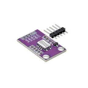
The MiCS-4514 is a dual-sensor gas detection module designed for air quality monitoring and industrial applications. It can simultaneously detect oxidizing gases (NO₂) and reducing gases (CO, NH₃, CH₄, ethanol, hydrogen), making it ideal for smart air quality systems and environmental monitoring.
⚡ Key Features
- Dual-Sensor Design – Detects both oxidizing and reducing gases.
- Independent Sensing Elements – Each with its own heater and sensitive layer for enhanced accuracy.
- Analog Voltage Output – Provides a signal proportional to gas concentration, readable via ADC.
- Ideal for Air Quality & Industrial Applications – Used in pollution monitoring, HVAC, and safety systems.
For additional air quality monitoring solutions, consider the CCS811, which detects TVOCs and eCO₂. 🚀
The MiCS-4514 offers a compact design with low power consumption and fast response time, making it suitable for portable devices, HVAC systems, and IoT applications. Its dual-element architecture provides flexibility for multi-gas detection in a single device.
Get Your MiCS-4514


💡 Prices are subject to change. We earn from qualifying purchases as an Amazon Associate.
MiCS-4514 Specifications
Complete technical specification details for MiCS-4514 Dual Gas Sensor
📊 Technical Parameters
MiCS-4514 Pinout
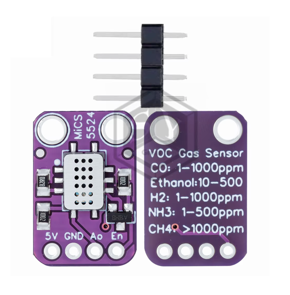
The MiCS-4514 features 6 pins for power, dual analog outputs (reducing/oxidizing gases), and heater control.
Visual Pinout Diagram
Pin Types
Quick Tips
Object],Independent sensing elements with separate heaters
Object],Analog outputs require ADC for reading
Object]
Pin Descriptions
| Pin Name | Type | Description | Notes |
|---|---|---|---|
1 Pin 1 (Vcc) | Power | Power supply input (5V). Powers the sensor circuitry. | Requires stable 5V supply. |
2 Pin 2 (GND) | Power | Ground connection. Connect to system ground. | |
3 Pin 3 (Reducing Gas Output) | Analog | Analog voltage output for reducing gases (CO, NH₃, CH₄, ethanol, H₂). | Read via ADC - voltage proportional to gas concentration. |
4 Pin 4 (Oxidizing Gas Output) | Analog | Analog voltage output for oxidizing gases (NO₂). | Read via ADC - voltage proportional to gas concentration. |
5 Pin 5 (Heater Control) | PWM | Heater control input (PWM). Controls heating element temperature. | Proper heating essential for accurate readings. |
6 Pin 6 (Heater Ground) | Power | Heater ground connection. Separate from signal ground. | Use current-limiting resistor if needed. |
Wiring MiCS-4514 to ESP32
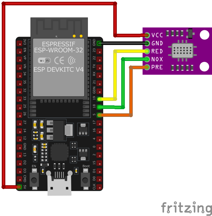
To interface the MiCS-4514 with an ESP32, connect Vcc to 5V, GND to ground, both gas outputs to ADC pins, and heater control to a PWM GPIO pin.
Visual Wiring Diagram
Connection Status
Protocol
Pin Connections
| MiCS-4514 Pin | Connection | ESP32 Pin | Description |
|---|---|---|---|
1 Pin 1 (Vcc) Required | 5V | Power supply (5V). Ensure supply can provide sufficient current. | |
2 Pin 2 (GND) Required | GND | Signal ground connection. | |
3 Pin 3 (Reducing Gas) Required | GPIO 34 (ADC1_CH6) | Analog output for CO, NH₃, CH₄, ethanol, H₂. Read via ADC. | |
4 Pin 4 (Oxidizing Gas) Required | GPIO 35 (ADC1_CH7) | Analog output for NO₂. Read via ADC. | |
5 Pin 5 (Heater Control) Required | GPIO 25 | PWM signal to control heater temperature. | |
6 Pin 6 (Heater GND) Required | GND | Heater ground connection. |
Object]
ESP32 ADC1 pins (GPIO 32-39) - avoid ADC2 if using WiFi
Object]
requires proper current limiting - check datasheet
required for absolute gas concentration values
readings are relative - use for gas presence detection
sensor in well-ventilated area during warm-up
MiCS-4514 Troubleshooting
Common issues and solutions to help you get your sensor working
Common Issues
Issue: The MiCS-4514 sensor is not recognized on the I2C bus, leading to initialization failures.
Possible causes include incorrect I2C address configuration, improper wiring connections, or faulty sensor hardware.
Solution: Verify the sensor's I2C address using an I2C scanner and ensure it matches the address defined in your code. The default I2C address is 0x75. Check all wiring connections to ensure they are secure and correctly aligned with the microcontroller's I2C pins. If the sensor is still not detected, consider testing with a different sensor to rule out hardware defects.
Issue: The sensor outputs 0.00 ppm for all gas parameters (e.g., CO, NO2, NH3, C2H5OH) despite proper connections.
Possible causes include insufficient warm-up time, incorrect sensor initialization, or faulty sensor hardware.
Solution: Allow the sensor to warm up for at least 3 minutes after powering on, as it requires this time to stabilize. Ensure that the sensor is properly initialized in your code and that the correct I2C address is specified. If the issue persists, the sensor may be defective and require replacement.
Issue: The sensor provides gas concentration readings that are significantly off from expected values.
Possible causes include improper calibration, environmental factors affecting sensor performance, or incorrect data interpretation in the code.
Solution: Calibrate the sensor in a controlled environment to establish accurate baseline readings. Ensure the sensor is placed in an environment free from contaminants that could affect its performance. Review your code to confirm that the data from the sensor is being interpreted correctly, considering any necessary conversion factors.
Issue: The sensor outputs gas concentration readings that fluctuate wildly, making it difficult to obtain stable measurements.
Possible causes include an unstable power supply, external electromagnetic interference, or faulty sensor hardware.
Solution: Use a stable and regulated power supply to power the sensor. Ensure that the sensor and its connections are shielded from sources of electromagnetic interference. If the problem persists, consider replacing the sensor, as it may be defective.
Debugging Tips
Use the Serial Monitor to check for error messages and verify the sensor's output. Add debug prints in your code to track the sensor's state.
Use a multimeter to verify voltage levels and check for continuity in your connections. Ensure the power supply is stable and within the sensor's requirements.
Additional Resources
MiCS-4514 Programming Examples
Ready-to-use code examples for different platforms and frameworks
#include <Wire.h>

const int reducingGasPin = 19; // Analog input for reducing gas
const int oxidizingGasPin = 18; // Analog input for oxidizing gas
const int heaterPin = 5; // Digital output for heater control

void setup() {
    Serial.begin(9600);

    // Configure heater pin
    pinMode(heaterPin, OUTPUT);
    digitalWrite(heaterPin, HIGH); // Turn on the heater
}

void loop() {
    int reducingGasValue = analogRead(reducingGasPin);
    int oxidizingGasValue = analogRead(oxidizingGasPin);

    // Convert analog values to voltage
    float reducingGasVoltage = reducingGasValue * (5.0 / 1023.0);
    float oxidizingGasVoltage = oxidizingGasValue * (5.0 / 1023.0);

    Serial.print("Reducing Gas Voltage: ");
    Serial.print(reducingGasVoltage);
    Serial.println(" V");

    Serial.print("Oxidizing Gas Voltage: ");
    Serial.print(oxidizingGasVoltage);
    Serial.println(" V");

    delay(1000);
}#include <stdio.h>
#include "driver/adc.h"
#include "esp_adc_cal.h"
#include "driver/gpio.h"
#define REDUCING_GAS_CHANNEL ADC1_CHANNEL_7 // GPIO19
#define OXIDIZING_GAS_CHANNEL ADC1_CHANNEL_6 // GPIO18
#define HEATER_PIN GPIO_NUM_5
#define DEFAULT_VREF 1100
void app_main(void) {
// Configure heater pin
gpio_pad_select_gpio(HEATER_PIN);
gpio_set_direction(HEATER_PIN, GPIO_MODE_OUTPUT);
gpio_set_level(HEATER_PIN, 1); // Turn on the heater
// Configure ADC
adc1_config_width(ADC_WIDTH_BIT_12);
adc1_config_channel_atten(REDUCING_GAS_CHANNEL, ADC_ATTEN_DB_11);
adc1_config_channel_atten(OXIDIZING_GAS_CHANNEL, ADC_ATTEN_DB_11);
esp_adc_cal_characteristics_t *adc_chars = calloc(1, sizeof(esp_adc_cal_characteristics_t));
esp_adc_cal_characterize(ADC_UNIT_1, ADC_ATTEN_DB_11, ADC_WIDTH_BIT_12, DEFAULT_VREF, adc_chars);
while (1) {
uint32_t reducing_raw = adc1_get_raw(REDUCING_GAS_CHANNEL);
uint32_t oxidizing_raw = adc1_get_raw(OXIDIZING_GAS_CHANNEL);
uint32_t reducing_voltage = esp_adc_cal_raw_to_voltage(reducing_raw, adc_chars);
uint32_t oxidizing_voltage = esp_adc_cal_raw_to_voltage(oxidizing_raw, adc_chars);
printf("Reducing Gas Voltage: %d mV\n", reducing_voltage);
printf("Oxidizing Gas Voltage: %d mV\n", oxidizing_voltage);
vTaskDelay(pdMS_TO_TICKS(1000));
}
}sensor:
- platform: adc
pin: GPIO19
name: "Reducing Gas Voltage"
update_interval: 1s
- platform: adc
pin: GPIO18
name: "Oxidizing Gas Voltage"
update_interval: 1s
gpio:
- platform: output
pin: GPIO5
id: heater_control
interval:
- interval: 1s
then:
- output.turn_on: heater_controlplatformio.ini
[env:esp32dev]
platform = espressif32
board = esp32dev
framework = arduino
monitor_speed = 115200
main.cpp
#include <Arduino.h>

const int reducingGasPin = 19; // Analog input for reducing gas
const int oxidizingGasPin = 18; // Analog input for oxidizing gas
const int heaterPin = 5; // Digital output for heater control

void setup() {
    Serial.begin(115200);

    // Configure heater pin
    pinMode(heaterPin, OUTPUT);
    digitalWrite(heaterPin, HIGH); // Turn on the heater
}

void loop() {
    int reducingGasValue = analogRead(reducingGasPin);
    int oxidizingGasValue = analogRead(oxidizingGasPin);

    float reducingGasVoltage = reducingGasValue * (3.3 / 4095.0);
    float oxidizingGasVoltage = oxidizingGasValue * (3.3 / 4095.0);

    Serial.print("Reducing Gas Voltage: ");
    Serial.print(reducingGasVoltage);
    Serial.println(" V");

    Serial.print("Oxidizing Gas Voltage: ");
    Serial.print(oxidizingGasVoltage);
    Serial.println(" V");

    delay(1000);
}from machine import ADC, Pin
import time
# Pin definitions
reducing_adc = ADC(Pin(19)) # Analog input for reducing gas
oxidizing_adc = ADC(Pin(18)) # Analog input for oxidizing gas
heater_pin = Pin(5, Pin.OUT) # Digital output for heater control
# Configure ADC
reducing_adc.atten(ADC.ATTN_11DB)
oxidizing_adc.atten(ADC.ATTN_11DB)
# Turn on the heater
heater_pin.on()
while True:
reducing_voltage = reducing_adc.read() * (3.3 / 4095)
oxidizing_voltage = oxidizing_adc.read() * (3.3 / 4095)
print(f"Reducing Gas Voltage: {reducing_voltage:.2f} V")
print(f"Oxidizing Gas Voltage: {oxidizing_voltage:.2f} V")
time.sleep(1)Wrapping Up MiCS-4514
The ESP32 MiCS-4514 Dual Gas Sensor is a powerful Air Quality sensor that offers excellent performance and reliability. With support for multiple development platforms including Arduino, ESP-IDF, ESPHome, PlatformIO, and MicroPython, it's a versatile choice for your IoT projects.
Best Practices
For optimal performance, ensure proper wiring and follow the recommended configuration for your chosen development platform.
Safety First
Always verify power supply requirements and pin connections before powering up your project to avoid potential damage.
Ready to Start Building?
Now that you have all the information you need, it's time to integrate the MiCS-4514 into your ESP32 project and bring your ideas to life!
Explore Alternative Sensors
Looking for alternatives to the MiCS-4514? Check out these similar sensors that might fit your project needs.
AGS10 Sensor
The AGS10 is a gas sensor known for detecting a range of gases, including methane, propane, and hydrogen. Designed with stability and...
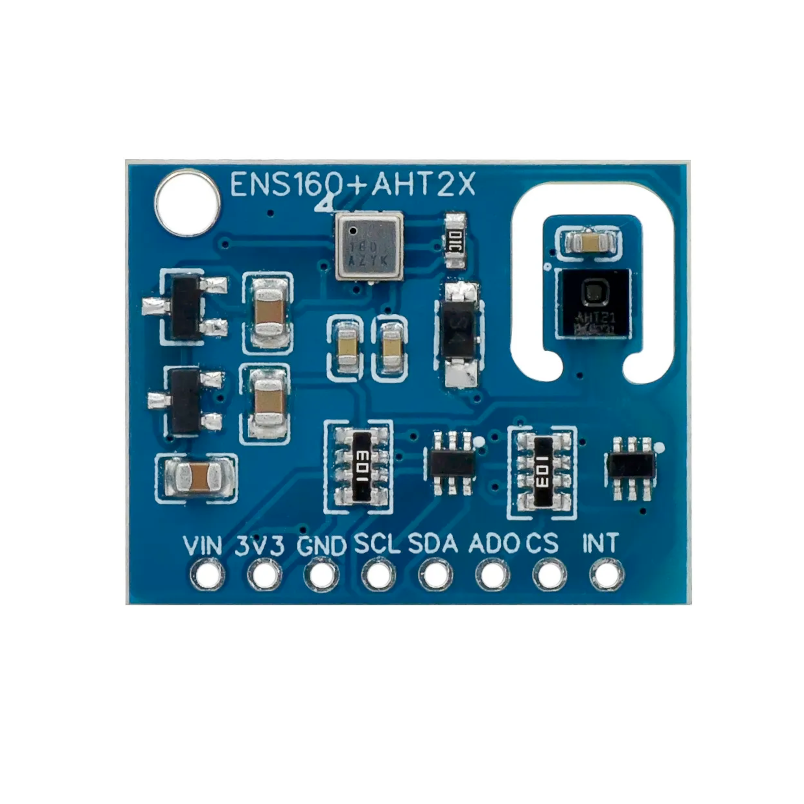
ENS160 Digital Metal-Oxide Multi-Gas Sensor
The ENS160 is a digital MOX gas sensor optimized for indoor air quality monitoring. It provides accurate measurements of TVOC and eCO₂...
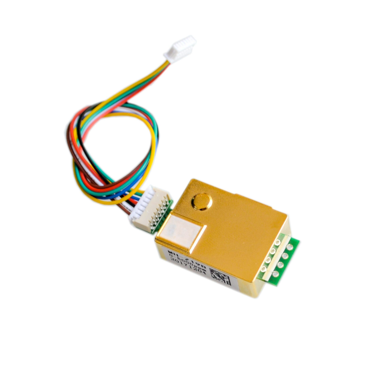
MH-Z19 NDIR CO₂ Sensor
The MH-Z19 is a high-accuracy CO₂ sensor using NDIR technology, suitable for air quality monitoring. It supports UART and PWM communication,...


