
SIM868 GSM/GPRS + GNSS Module
The SIM868 is a versatile GSM/GPRS module with integrated GNSS functionality, providing reliable communication and navigation capabilities for various applications. Its compact design and multiple interfaces make it an ideal choice for projects requiring both cellular connectivity and precise positioning.

SIM868 pinout
The SIM868 pinout includes power, UART communication for GSM and GPS, control, status indication, dual antenna connections (cellular and GPS), and SIM card interface pins for quad-band GSM/GPRS and enhanced GPS functionality.
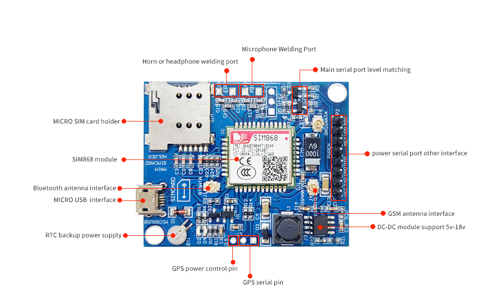
| Pin | Type | Description | Notes |
|---|---|---|---|
| VBAT | Power | Power supply input (3.4V to 4.4V) | Requires stable power supply with peak current up to 2A |
| GND | Ground | Ground connection | Connect to common ground |
| TXD | UART TX | UART Transmit Data for GSM (connects to microcontroller RX) | Default baud rate: 9600 bps |
| RXD | UART RX | UART Receive Data for GSM (connects to microcontroller TX) | Default baud rate: 9600 bps |
| PWRKEY | Control | Power on/off control (active low) | Pull low for at least 1 second to power on |
| NETLIGHT | Status | Network status indication | LED indicator for network registration status |
| STATUS | Status | Module operating status indication | Shows module power state |
| GPS_VCC | Power | GPS power supply | Power supply for GPS module (3.3V) |
| GPS_TX | UART TX | GPS UART Transmit Data | GPS data output (NMEA sentences) |
| GPS_RX | UART RX | GPS UART Receive Data | GPS command input (optional) |
| ANT_GSM | Antenna | GSM antenna connection | Requires external GSM antenna |
| ANT_GPS | Antenna | GPS antenna connection | Requires external GPS antenna |
Quad-band GSM/GPRS module (850/900/1800/1900MHz) with enhanced GPS
Enhanced GPS performance compared to SIM808
Supports voice calls, SMS, GPRS data transfer, and GPS location tracking
GPS supports up to 66 channels for satellite tracking
Improved GPS sensitivity: -165dBm tracking, -148dBm acquisition
Dual UART interfaces: one for GSM, one for GPS
Requires SIM card for cellular connectivity
Power consumption: 2A peak during transmission
Default GSM UART baud rate: 9600 bps
Wiring the SIM868 to ESP32
Connect the SIM868 to your ESP32 via dual UART for AT command communication (GSM) and GPS data reception. The module requires a stable 3.4V-4.4V power supply with sufficient current capacity (peak 2A). External antennas are required for both GSM and GPS functionality.
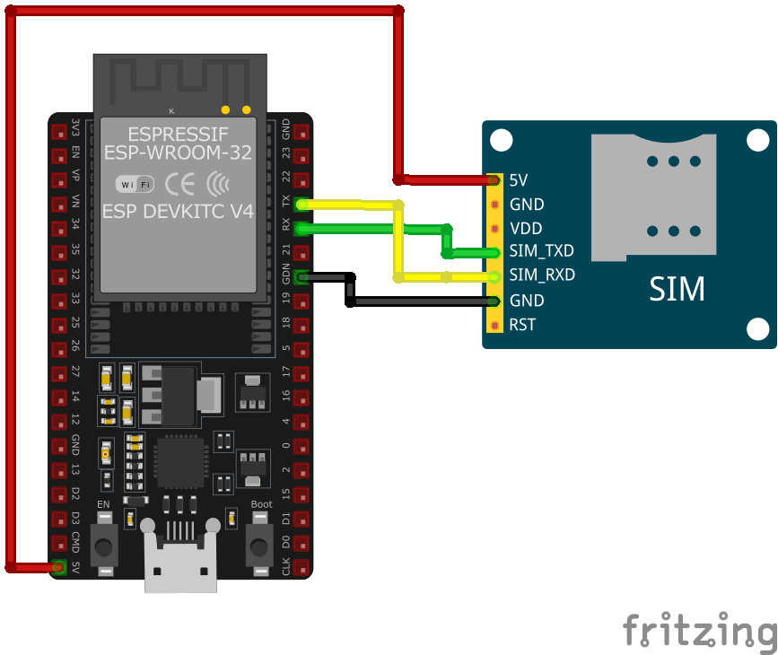
| SIM868 pin | ESP32 pin | Purpose |
|---|---|---|
| VBAT | 3.7V-4.4V Power Supply | Provide stable power (NOT from ESP32 pin) |
| GND | GND | Common ground connection |
| TXD | GPIO16 (RX2) | SIM868 GSM TX to ESP32 RX |
| RXD | GPIO17 (TX2) | SIM868 GSM RX to ESP32 TX |
| GPS_VCC | 3.3V | GPS module power supply |
| GPS_TX | GPIO18 | GPS data output to ESP32 |
| GPS_RX | GPIO19 | GPS command input (optional) · optional |
| PWRKEY | GPIO4 | Power control (pull low to power on) · optional |
| ANT_GSM | External GSM Antenna | Connect GSM antenna |
| ANT_GPS | External GPS Antenna | Connect GPS antenna |
CRITICAL: Use a dedicated power supply (3.4V-4.4V, 2A peak) - DO NOT power from ESP32 pin!
Enhanced GPS performance compared to SIM808
Dual UART setup: one for GSM AT commands, one for GPS NMEA data
Default GSM UART baud rate is 9600 bps
GPS outputs NMEA sentences at 9600 bps
External GSM antenna is mandatory for network connectivity
External GPS antenna is mandatory for location tracking
GPS requires clear view of the sky for satellite acquisition
Pull PWRKEY low for at least 1 second to power on the module
Monitor NETLIGHT pin for network registration status
Insert active SIM card before powering on
GPS_VCC can be powered from ESP32 3.3V pin (low current)
Ensure good antenna placement for optimal signal reception
SIM868 code examples
// SIM868 on ESP32 UART2: module TXD -> GPIO16 (RX2), RXD -> GPIO17 (TX2), PWRKEY -> GPIO4
#define PWRKEY_PIN 4
#define MODEM_BAUD 9600

HardwareSerial modem(2); // UART2

void powerOnModem() {
    pinMode(PWRKEY_PIN, OUTPUT);
    digitalWrite(PWRKEY_PIN, LOW);
    delay(1200); // Hold PWRKEY low to power the module on
    digitalWrite(PWRKEY_PIN, HIGH);
    delay(5000); // Give the module time to boot and register
}

void sendATCommand(const char *command) {
    modem.println(command);
    delay(500);
    while (modem.available()) {
        Serial.write(modem.read());
    }
}

void setup() {
    Serial.begin(115200);
    modem.begin(MODEM_BAUD, SERIAL_8N1, 16, 17); // RX=GPIO16, TX=GPIO17

    powerOnModem();

    Serial.println("Testing AT communication...");
    sendATCommand("AT");       // Should answer OK
    sendATCommand("ATI");      // Module identification
    sendATCommand("AT+CSQ");   // Signal quality
    sendATCommand("AT+CREG?"); // Network registration status
}

void loop() {
    // Bridge the Serial Monitor and the modem so you can type AT commands directly
    while (Serial.available()) modem.write(Serial.read());
    while (modem.available()) Serial.write(modem.read());
}
This sketch talks to the SIM868 over the ESP32's second hardware UART (UART2, RX on GPIO16, TX on GPIO17) - the ESP32 has three hardware UARTs, so the AVR-style SoftwareSerial library is neither available nor needed. GPIO4 pulses the module's PWRKEY to power it on, then a few basic AT commands verify communication, signal quality and network registration. The loop bridges the Serial Monitor to the module so you can type further AT commands interactively. Power the module from a supply that can deliver its transmit-burst current - not from the ESP32's 3.3V regulator.
#include <stdio.h>
#include <string.h>
#include "driver/uart.h"
#include "driver/gpio.h"
#include "freertos/task.h"

#define TX_PIN 17
#define RX_PIN 16
#define PWRKEY_PIN 4
#define UART_PORT UART_NUM_1

void init_uart() {
    uart_config_t uart_config = {
        .baud_rate = 9600,
        .data_bits = UART_DATA_8_BITS,
        .parity = UART_PARITY_DISABLE,
        .stop_bits = UART_STOP_BITS_1,
        .flow_ctrl = UART_HW_FLOWCTRL_DISABLE
    };

    uart_param_config(UART_PORT, &uart_config);
    uart_set_pin(UART_PORT, TX_PIN, RX_PIN, UART_PIN_NO_CHANGE, UART_PIN_NO_CHANGE);
    uart_driver_install(UART_PORT, 1024, 0, 0, NULL, 0);
}

void power_on_sim868() {
    gpio_set_direction(PWRKEY_PIN, GPIO_MODE_OUTPUT);
    gpio_set_level(PWRKEY_PIN, 0);
    vTaskDelay(1000 / portTICK_PERIOD_MS); // Hold PWRKEY low for 1 second
    gpio_set_level(PWRKEY_PIN, 1);
    vTaskDelay(5000 / portTICK_PERIOD_MS); // Wait for the module to initialize
}

void app_main(void) {
    init_uart();
    power_on_sim868();

    char *test_cmd = "AT\r\n";
    uart_write_bytes(UART_PORT, test_cmd, strlen(test_cmd));

    while (true) {
        char data[128];
        int len = uart_read_bytes(UART_PORT, data, sizeof(data), 100 / portTICK_PERIOD_MS);
        if (len > 0) {
            data[len] = '\0';
            printf("Response: %s\n", data);
        }
        vTaskDelay(1000 / portTICK_PERIOD_MS);
    }
}
This ESP-IDF example initializes UART communication with the SIM868 module and powers it on using the PWRKEY pin (GPIO4). The UART interface is configured with GPIO17 as TX and GPIO16 as RX. An AT command is sent to test communication, and responses from the module are printed to the console. This code can be extended to include GPS functionality or handle SMS and GPRS data transmission.
uart:
  tx_pin: GPIO17  # module RXD
  rx_pin: GPIO16  # module TXD
  baud_rate: 9600

# ESPHome's sim800l component speaks the generic SIM AT command set
sim800l:
  on_sms_received:
    - logger.log:
        format: "Received '%s' from %s"
        args: [ 'message.c_str()', 'sender.c_str()' ]
ESPHome's sim800l component speaks the SIM800/SIM900 AT command set, which the SIM868 shares - the old custom-platform example no longer works (that component was removed from ESPHome in 2025). Wire UART2 as shown (9600 baud) and you get on_sms_received triggers plus sim800l.send_sms and USSD actions. Power the module from a supply that can deliver its transmit-burst current.
[env:sim868]
platform = espressif32
board = esp32dev
framework = arduino
monitor_speed = 115200#include <HardwareSerial.h>
#include <Arduino.h>
HardwareSerial sim868(1);
#define PWRKEY 4
void power_on_sim868() {
pinMode(PWRKEY, OUTPUT);
digitalWrite(PWRKEY, LOW);
delay(1000); // Hold PWRKEY low for 1 second
digitalWrite(PWRKEY, HIGH);
delay(5000); // Wait for initialization
}
void setup() {
Serial.begin(115200);
sim868.begin(9600, SERIAL_8N1, 16, 17); // RX, TX
power_on_sim868();
// Test AT command
sim868.println("AT");
delay(1000);
while (sim868.available()) {
Serial.write(sim868.read());
}
// Send SMS
sim868.println("AT+CMGF=1"); // Set SMS to text mode
delay(1000);
sim868.println("AT+CMGS=\"+1234567890\""); // Replace with recipient's number
delay(1000);
sim868.print("Hello from SIM868");
sim868.write(26); // CTRL+Z to send SMS
delay(5000);
}
void loop() {
// Handle incoming data or other functionalities
}This PlatformIO code interfaces with the SIM868 module using HardwareSerial on an ESP32. The power_on_sim868 function toggles the PWRKEY pin (GPIO4) to activate the module. The AT command is sent to test communication, and SMS functionality is implemented in the setup. Additional GPS or GPRS handling can be added in the loop.
from machine import UART, Pin
import time

# Initialize UART
uart = UART(2, baudrate=9600, tx=17, rx=16)
pwrkey = Pin(4, Pin.OUT)

def power_on_sim868():
    pwrkey.value(0)
    time.sleep(1)  # Hold PWRKEY low for 1 second
    pwrkey.value(1)
    time.sleep(5)  # Wait for module to initialize

def send_at(command):
    uart.write(command + '\r\n')
    time.sleep(1)
    while uart.any():
        print(uart.read().decode('utf-8'), end='')

# Power on the module
power_on_sim868()

# Test communication
send_at('AT')

# Send SMS
send_at('AT+CMGF=1')  # Set SMS to text mode
send_at('AT+CMGS="+1234567890"')  # Replace with recipient's number
uart.write("Hello from MicroPython" + chr(26))
This MicroPython code communicates with the SIM868 module over UART. The power_on_sim868 function activates the module using the PWRKEY pin (GPIO4). The send_at function sends AT commands and prints the responses. The script initializes the module, tests communication, and demonstrates how to send an SMS. Additional logic for GNSS or GPRS data handling can be added.
SIM868 specifications
About the SIM868
The SIM868 shares its quad-band (850/900/1800/1900 MHz) GSM/GPRS engine and its compact 17.6 x 15.7 x 2.3 mm footprint with the SIM800C, but replaces plain GPS with a multi-constellation GNSS receiver - 33 tracking / 99 acquisition channels covering GPS, GLONASS and BeiDou (plus SBAS augmentation), at the same -165 dBm tracking sensitivity class as the older SIM808. Against the SIM808 specifically, that means a materially smaller board (SIM808 is 24 x 24 x 2.6 mm) alongside better fix reliability in places where GPS alone struggles - dense cities, valleys, anywhere a second or third constellation helps. Bluetooth is present via a dedicated antenna pad, same as SIM800C.
The same power rules from the rest of the SIM800 line apply: GSM runs on 3.4V to 4.4V and needs a supply that can deliver multi-amp bursts during transmission, while the GNSS section has its own, wider 2.9V to 4.4V rail - neither should come straight off the ESP32’s 3.3V regulator. And the same 2G caveat applies too: US carriers have retired 2G completely (T-Mobile’s GSM network, the last one operating, shut down on August 3, 2026), several EU carriers intend to keep some 2G running into the late 2020s or beyond for fallback and IoT traffic, and 2G in India remains commercially active with no announced shutdown date as of 2026 - so the cellular half of this module is only as useful as the deployment country’s 2G roadmap, independent of how good the GNSS half is.
For a new tracker design without a reason to stick with plain GPS, SIM868 is generally the better pick over SIM808 today. TinyGSM supports it directly. Where 2G itself is the risk rather than GNSS accuracy, SIM7600G carries the same kind of multi-constellation GNSS on an LTE Cat 1 radio instead, and for SMS-only or GPRS-only builds with no positioning need, SIM800L is the simpler, cheaper option.
SIM868 troubleshooting
Module Fails to Power On
›
Issue: The SIM868 module does not power up or respond to commands.
Possible causes include insufficient power supply, incorrect wiring, or faulty hardware.
Solution: Ensure the module is connected to a stable power source within the recommended voltage range of 3.4V to 4.4V. Verify that all connections are secure and correctly configured. If the problem persists, consider testing the module with a different power source or replacing it.
SIM Card Not Recognized
›
Issue: The module fails to detect or register the SIM card.
Possible causes include improper SIM card insertion, unsupported SIM card type, or SIM card lock.
Solution: Ensure the SIM card is properly inserted into the module's SIM card slot and is compatible with the GSM network. Verify that the SIM card is active and unlocked. If necessary, test the SIM card in another device to confirm its functionality.
Poor Network Signal or Connectivity Issues
›
Issue: The module experiences weak signal strength or fails to maintain a stable network connection.
Possible causes include improper antenna connection, environmental interference, or network coverage limitations.
Solution: Ensure the GSM antenna is securely connected to the module and positioned for optimal signal reception. Avoid placing the module near sources of electromagnetic interference. Check the network coverage in your area to ensure adequate signal strength.
AT Commands Not Responding
›
Issue: The module does not respond to AT commands sent from the microcontroller or computer.
Possible causes include incorrect baud rate settings, faulty serial connections, or improper command syntax.
Solution: Verify that the baud rate of the module matches that of the microcontroller or computer; the default baud rate is 9600 bps. Check that the TX and RX lines are correctly connected and that there are no loose connections. Ensure that AT commands are correctly formatted and terminated with a carriage return.
GPS Functionality Not Working
›
Issue: The SIM868 module fails to acquire GPS signals or provide location data.
Possible causes include improper antenna connection, obstructed view of the sky, or GPS functionality not enabled.
Solution: Ensure the GPS antenna is properly connected and has a clear view of the sky to receive satellite signals. Verify that the GPS functionality is enabled by sending the appropriate AT commands to power on the GPS engine.
Where to buy the SIM868

Resources
Similar sensors


